Robotic system mimics human inspection tasks
Multicamera vision system performs surface-defect detection, OCV, and dimensional measurement on specialized parts.
When goods are produced in large volumes, automated machine-vision systems are often used as an integral part of the manufacturing process. However, products such as artificial human replacement parts or aircraft-motor engine components are produced in small quantities. These inspections are usually assigned to human operators. This is because of the complexity of each part and the difficulty of visualizing every surface at various angles and lighting conditions with static cameras and lighting assemblies.
“The level of complexity needed in automation systems directly relates to the amount of flexibility required,” says Sébastien Parent, a principal engineer with Averna Vision and Robotics (AV&R). “Inspecting various complex product shapes with highly reflective finishes and critical surface quality demand flexible machine-vision systems. These inspections are highly subjective.”
Human inspection
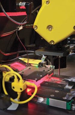
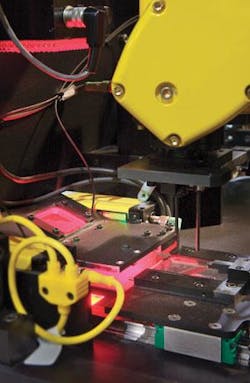
AV&R has developed a system that mimics human inspection using a robot, a combination of lighting, and multiple cameras. To simulate the operator sitting at a workstation moving the part between several inspection stations, a robot handles and moves parts so that multiple images can be obtained at different acquisition stations using off-the-shelf cameras, lighting, and I/O controllers.
According to Parent, the system is designed with the capability to learn new parts and determines the area of interest on these parts. “This provides the flexibility to inspect small batches of parts with varying dimensions,” he says, “exactly as a human being would.”
The configuration of the system is based on three different inspection tasks: surface-defect detection, optical character validation (OCV), and dimensional measurement. “Future versions will also integrate 3-D measurement to add depth information to the inspection for the surface-defect inspection,” says Parent.
For the robot to locate a part in its gripper, the part is first inserted in a holder that positions it within ±0.020 in. An LR Mate 200iB robot from Fanuc Robotics America then picks the part using the gripper to fine-tune the part positioning within 0.001-in. tolerance. After picking, the robot moves to the different acquisition stages to perform random surface-defect detection, OCV, and dimensional measurements. The communication between the robot LR Mate 200iB controller and the PC system host is performed via a PCI-6514 I/O board PCI-board from National Instruments.
A dual-processor-based PC performs image-processing tasks and controls the image-acquisition sequence by sending the command to the robot. The robot manages all I/Os of the inspection cell-security devices, proximity switches, sensors, pneumatic valves for the gripper, and activation of the illumination system. The advantage of this architecture is to optimize the machine-vision engine without spending processing resources in managing I/O resources.
Surface inspection
To perform surface inspection, the part is illuminated with a flat, diffuse LED light from Boreal Vision, and images are captured with a CV-M4CL Camera Link camera from JAI. “Using a robot in this type of application allows the part to be moved with six degrees of freedom, so the complete part can be viewed with the same acquisition system even if it has a complex shape,” says Parent.
Once image acquisition is performed, surface-inspection techniques developed at AV&R are used to analyze the surface of the part. After the robot positions the part in front of the camera, multiple images of the part are acquired with the part tilted and rotated at various angles. Thus, the state of a known part’s surface can be determined and compared with other parts. This camera is interfaced to the PC using one of the Camera Link ports of a NI PCIe-1430 acquisition board. In this inspection, the achieved resolution is 0.0015 in./pixel.
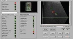
During inspection, anything other than this good surface is evaluated closely to determine if a defect exists and, if so, what type it is. “The system also evaluates different tolerances of specific areas of the inspected parts,” says Parent. For correct classification, defect criteria are based on a morphological analysis that determines whether any dents, scratches, die marks, grinding marks, pits, or discolorations exist. This analysis is performed using an NI particle-analysis virtual instrument.
After surface inspection, the system’s OCV station validates that the part model and the batch number marked on the part match the production batch. The system digitizes characters stamped or printed on each parts surface. To properly illuminate the part, the acquisition station uses an LED ringlight from Boreal Vision Solutions and a second CV-M4CL from JAI. This camera is interfaced to the PC using the second port of the NI PCIe-1430 Camera Link frame-grabber board. Based on the camera’s field of view, the resolution achieved in the inspection is 0.001 in./pixel. To perform OCV, AV&R chose the NI IMAQ OCR virtual instrument, part of NI LabVIEW 8.2.
A third station performs dimensional measurement. LED backlighting silhouettes the part. The part is again digitized with two P2-22-04K30 linescan cameras from DALSA, located 90° apart. When the robot moves the parts in this acquisition station, the cameras scan the part as in a photocopier machine. “Using the two orthogonal points of view and with a specially designed gripper, robot-positioning imprecision is compensated for during part scanning,” says Parent.
Both DALSA linescan cameras are interfaced to the ports of a second NI PCIe-1430 acquisition board. At this inspection station, the target uses a combination of cameras and algorithms with enough resolution and precision to target a gauge R&R of 10% for all the needed measurements. “One of our challenges was to guarantee a measurement precision of ±0.001 in. Because the system needs to image a volumetric object approximately 1.5 in. deep, the selection of the lenses was critical,” says Parent. For this reason, Averna chose to deploy two telecentric lenses from Jenoptik.
Vision software
“LabVIEW software optimizes multitasking to keep the processing time short. At present, the overall cycle time for each part inspected for the three tasks is less than 10 s, but this is directly related to the amount of manipulation needed by the robot to inspect each part,” says Parent. “The trick is to perform the image acquisition and processing independently. The system then can optimize the processing during robot movement, avoiding delays of a standard serial image-processing sequence.
“NI LabVIEW software provides a library of powerful mathematical algorithms that are useful when image interpolation needs to be performed to increase software measurement precision,” says Parent. To ensure consistency, a calibration check validates system operation. This is performed by loading a master part, inspecting it, and comparing the results with previous values in memory.
“To emulate human flexibility, a learning procedure is included. This ensures that the customer can add new product data,” says Parent. At present, the system is configured for parts with a maximum size of 3 × 1.5 × 1.5 in. However, AV&R is working to develop similar applications for parts as large as 3 ft long × 1 ft diameter.
null


