Processor targets medical, video applications
One of the highlights of the recent SPIE Defense & Security Symposium (Orlando FL, USA; March 2008) was the demonstration by Ambric (Beaverton, OR, USA; www.ambric.com) of its Am2045 massively parallel processor (MPPA) device and aDesigner software. Designed as a multiple instruction, multiple data (MIMD) processor, the Am2045 has 336, 350-MHz 32-bit fixed point RISC processors, 168 of which are streaming RISC processors with DSP extensions (SRDs); the remaining 168 processors act as streaming RISC processors (SRs) that act as general-purpose processors.
“To be successful in entering the parallel-processing market we initially needed to select a few target applications to demonstrate our MPPA’s performance and its ease of programming and scalability,” said Paul Chen, director of strategic business development at Ambric. “One of the largest of these—the advanced video processing market—demands fast HD MPEG-2 and HD H.264 encoding.” Because of this, Ambric developed a PCI Express video accelerator reference board design for OEM customers.
The first end-user product to market is Pyro Kompressor HD being sold by the Pyro AV division of ADS Tech (Cerritos, CA, USA; www.pyroav.com) to accelerate HD MPEG-2 and HD H.264 encoding, which results in encoding that is many times faster than software-only video compression for high video-quality authoring and distribution. Sorenson Media (Salt Lake City, UT, USA; www.sorensonmedia.com) is also shipping its transcoding application, which is transparently integrated with Ambric’s hardware in a product called Squeeze 5 Pro Juiced.
“Of course Ambric’s multiprocessor device is also suitable for other applications, most notably medical-imaging systems and military applications,” says Chen. Indeed, the company has already discussed and benchmarked the device in two white papers on ultrasound digital beam-forming and CT back-projection. To understand why Ambric’s processor is especially suited for these applications requires both an examination of the hardware and the software offered by the company.
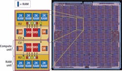
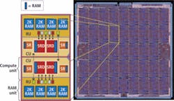
FIGURE 1. In the Am2045 architecture, four processors make up a compute unit (CU) that consists of two RISC processors with DSP extensions (SRDs) for processing image data and two RISC processors (SRs) for managing channel traffic and generating addresses. Two clusters of these CUs make up a top-level physical building-block called a bric and the core of the chip is assembled by stacking up brics.
In the Am2045 architecture, a cluster of four processors make up a compute unit (CU). This CU has two SRDs for processing image data and two SRs for managing channel traffic and generating addresses. Two clusters of these CUs make up a top-level physical building-block called a bric, and the core of the chip is assembled by stacking up brics (see Fig. 1). Each bric has two computer unit-RAM unit (RU) pairs that connect through channels that cross bric-to-bric.
Indeed, it is the use of these contiguous bric-to-bric channels that allows logically divided sections of code to be run independently on multiple processors. “The Ambric programming model assumes that a modern chip can integrate so many processors that each processor can run its own task and doesn’t need to implement complex and time-consuming task switching,” says Chen. “Each channel is wordwide, unidirectional, and point-to-point, and individual processors are synchronized to this channel activity. If, for example, a processor running a task outputs a word to a channel that is full, the processor automatically stalls until space is available. The same is true when a processor running a task tries to input data from an empty channel.”
As with any parallel-processing implementation, data dependencies exist. If the results from one processor, for example, must be used by another to accomplish a final result, there will be a pipeline delay. One of the ways conventional compliers overcome these problems is by loop unrolling or splitting so that either multiple iterations of the code loop are executed concurrently or the problem is split into independent chunks of code that can be executed concurrently. To be most effective, any data parallelism must be mapped to the processor array at development time.
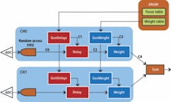
FIGURE 2. In the design of a two-channel ultrasound beam former, black lines represent channels connecting objects and arrows indicate the direction of data flow between objects. While most of the objects consist of primitive objects such as delays and weights, Chan0 and Chan1 are complex objects that are composed of a number of these primitive objects.
In Ambric’s approach, the developer describes an application as a high-level block diagram that consists of a parallel structure of objects and the data and control messages they send and receive. Based on the Eclipse open development platform from the Eclipse Foundation (www.eclipse.org), the company’s aDesigner integrated development environment (IDE) lets objects be written in a subset of standard Java or assembly code. One example is the design of a two-channel ultrasound beam former (see Fig. 2). While most of the objects consist of primitive objects such as delays and weights, Chan0 and Chan1 are complex objects that are composed of a number of these primitive objects.
Once defined, the block diagram can be transformed into a design that runs on the Ambric processor. First, primitive objects are defined using aStruct, a text-based tool that describes objects, their I/O interfaces, channel connection topology, and the code (delay.java) that runs on the processor. In this case, the object description of the primitive Delay object that performs a 6-tap FIR on the data is
interface Delay { // Define the object Delay
inbound delayIn, USA; // input port for samples already focused
inbound in, USA; // input port for FIR coefficients
outbound out, USA; // output for weight processing }
binding bDelay implements Delay { // Bind source code to object
implementation “Delay.java”, USA;
After other primitive objects are defined, complex objects such as Chan can be defined using aStruct. This describes the primitive objects such as Delay and their channel connection topology for Chan. Creating a complex object like Chan enables designers to scale designs by simple object repetition without requiring any further design.
binding cChan implements Chan {
channel c0 = {in, Delay.in}, USA;
channel c1 = {GenDelays.out, Delay.delayIn}, USA;
channel c2 = {Delay.out, Weight.in}, USA;
channel c3 = {GenWeights.out, Weight.weightIn}, USA;
channel c4 = {Weight.out, out}, USA;
After a design’s execution behavior is simulated, a binary file can be downloaded to an Ambric device over a four-lane PCI Express interface. Then, Ambric’s debugging tools allow developers to set breakpoints, examine processor status, and poke data in memory or FIFOs.


