Spanning the Spectrum
Andrew Wilson, Editor
To produce the most cost-effective machine-vision systems, system integrators must juggle with the disparate fields of electrical, mechanical, optical, and electronic engineering. After determining the task to be performed by the system, developers must then evaluate multiple lighting, lens, optic, frame grabber, and camera products with which to perform the task. To make matters more complex, the number of different applications that can be solved using these components ranges from agricultural inspection to aerospace parts analysis, each of which demands a different array of product components.
Before embarking on such a task, system integrators must be aware of the effects poor illumination can have. If a part is incorrectly lit or the wrong camera/lens combination is used, the resulting images may show poor contrast. Many times, poor hardware choices result in months of work spent coding image-processing algorithms to solve what could have been accomplished far more easily if the correct lighting or lens/camera combination had been chosen.
To help alleviate these types of problems, hundreds of different lighting products are now available that combine a number of illumination technologies, spectral characteristics, and configurations. Illumination methods include xenon, mercury, halogen, fluorescent, and LED illumination, each of which posses their own characteristics such as luminous intensity and spectral content. Furthermore, each of these different technologies can be offered in backlighting, or brightfield or darkfield lighting configurations.
Spectral content
In his excellent article “A Practical Guide to Machine Vision Lighting,” Daryl Martin of Advanced illumination points out that it is important to evaluate both the brightness of any source of lighting and its spectral content [1]. By doing so, system developers can more easily understand which wavelength (if not configuration) of lighting product may be most useful. For this reason, along with their long lifetimes, relatively high power output, and stability, LEDs have become one of the most popular methods of illumination in today’s vision systems.
To date, a number of semiconductor vendors offer LEDs that range from the ultraviolet (UV) to the IR spectrum. For those wishing to evaluate the many thousands of different LEDs now available with which to design illumination products, Roithner LaserTeknik has developed a comprehensive web site that lists LEDs ranging from 255 nm (UV) to 1550 nm (IR).
While most current LEDs used by vendors of machine-vision lighting fall in the 380–760-nm visible region, the emergence of both UV and IR LEDs may eventually displace fluorescent and incandescent lamps currently used for this purpose. Just three months ago, Seoul Semiconductor announced no less than four UV LEDs, known as BioUV detectors that span the 255–310-nm range. To replace the UV mercury lamps currently used in a range of currency forgery-detection systems, M-Vision will use these LEDs in a portable fluorescent detector.
Luminous output
At present, UV devices do not offer the high luminous power output of their visible spectrum counterparts; they are not inexpensive, either, with the cost per LED in excess of $400. Because of this, machine-vision lighting suppliers such as Moritex USA have chosen to use less expensive 365-nm wavelength LEDs in their products. Based on these LEDs, Moritex now offers a number of ringlights, bar lights, and oblique square lights aimed at machine-vision illumination.
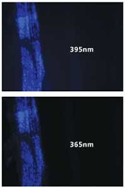
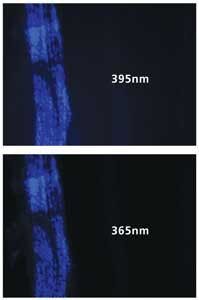
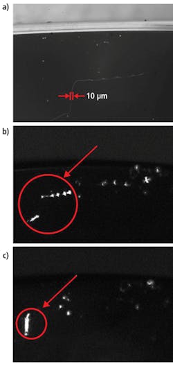
According to Matt Pinter of Smart Vision Lights, these 365-nm LEDs are still up to 10 times more expensive than 395-nm LEDs and in very short supply. However, by using a 395-nm LED and applying the correct lens filter, a lower-cost alternative can be developed (see Fig. 1).
To qualify these devices, LED vendors supply data based on the radiant flux emitted since LEDs that emit radiation outside the 380–760-nm spectrum have little visible optical output. For example, although the BioUV 255-nm LED from Seoul Semiconductor may have a radiant flux between 100–150 µW, the 365-nm UVTOP LED from Sensor Electronic Technology is specified as between 480–800 µW, or approximately five times more powerful.
While this data can be used to compare LED illumination systems outside the visible 380–760-nm range, it is far more common to find LED light output for products between these wavelengths given in either lumens or candelas. Unlike radiant flux (which measures the total power of the light emitted), the lumen (a measure of luminous flux) reflects the sensitivity of the human eye to different wavelengths, while the candela provides a measure of the power of the light in a particular direction.
Red, green, and blue
Like their IR counterparts, LEDs offered in the visible spectrum are narrow-bandwidth illumination devices that differ in the power of light produced. In its C5SMF-RJS range of LEDs, Cree offers blue, green, and red devices with dominant wavelengths of 470, 527, and 621 nm and light output power of 550–2130, 2130–8200, and 1100–4180 cd, respectively.
When using these different types of LEDs in a machine-vision application, it is important to consider the spectral reflectance of the object under test. Since like colors reflect, any red surface illuminated with red light will appear bright. Similarly, opposing colors absorb so that a green PCB illuminated with red light will appear dark. In choosing LED-based illumination systems, developers can use a color wheel to determine which color to use in illuminating objects (see Fig. 2).
Just as counterfeit detection, semiconductor, and biofluorescence applications will benefit from development in the UV range of the spectrum, so too will applications emerge that take advantage of IR LEDs. At present, a number of manufacturers, including Osram Opto Semiconductor, offer devices at peak wavelengths from 850–950 nm.
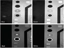
Like their UV and visible counterparts, IR LEDs also feature a relatively narrow spectral bandwidth. This makes their illumination particularly useful in machine-vision applications where it may be necessary to reduce the effects of visible artifacts to provide dimensional characteristic measurements. For example, using off-axis illumination to illuminate a yogurt package may result in many different features such as package color and barcodes being captured by color or monochrome cameras. Illuminating this package under IR light, however, can be used to reduce the color data, making dimensional package measurements easier and faster (see Fig. 3).
null
Combined colors
Of course, some machine-vision systems may require a broader spectrum of light. For this reason, many machine-vision lighting vendors offer red, green, and blue LED illumination products to create a white light. By combining these LEDs into a single unit, individual color output can be adjusted to a number of different visible spectral responses. In its range of Sirius ringlights, for example, Mightex Systems includes an RGB model that enables independent control of intensities of RGB colors. The company’s near IR model provides illumination at 880 nm for biomedical and machine-vision applications.
While choosing the correct illumination wavelength is of paramount importance in any lighting system, it only represents one of the factors that must be considered. Just as important are understanding the intricacies of the part being imaged, the configurations of the LED illumination system, and the type of camera used.
While every machine-vision application may demand a different spectrum of illumination, the configurations of the illumination systems—whether using ringlights, darkfield lights, backlights, coaxial lights, continuous diffuse lights, or dome lights—and the effects they have on part illumination have been clearly documented and illustrated by companies such as Microscan.
The camera is just as critical as the spectrum and type of lighting employed. Depending on the application, mismatching the spectral response of the camera with the lighting may require a higher amount of illumination or a camera more sensitive in the UV or IR spectrum.
Although narrow-frequency LED illumination systems may remain the mainstay of LED lighting vendors for years to come, the trend toward incorporating multiple-frequency illumination will continue as LED prices decrease. Just as camera vendors are only now incorporating multiple sensors to detect frequencies across multiple wavelengths, expect lighting vendors to follow suit, packaging LEDs of different wavelengths to meet a broad spectrum of applications.
Reference
1. D. Martin, “A Practical Guide to Machine Vision Lighting,” Advanced illumination web site, http://www.advill.com/content.php?sid=09fe9b933ddda421f62e042c32bdc102 (October 2007).
Smart lenses and lighting image edges optically
Every year image sensor manufacturers develop devices with smaller pixel sizes to a point where sensors with pixel sizes of 1.4 μm are now commercially available. However, to take full advantage of this resolution, the lens performance limits of cameras that use these sensors must also be evaluated. Because traditional telecentric lenses operate in the visible wavelength range, their maximum resolving power is diffraction limited and cannot be used to exploit the resolution of high-resolution sensors.
Since the diffraction limit of a lens is inversely proportional to the wavelength of light, lenses that operate in the 365–425-nm UV range will produce a greater resolution than those designed for the visible spectrum. In applications such as semiconductor inspection, this increased resolution is important since very small defects must often be detected.
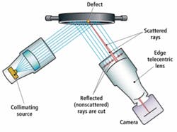
In these applications, telecentric lenses are often combined with collimated lighting to ensure even illumination of the part, allowing the edges of any defects to be accurately determined. To accomplish this defect detection optically, Opto Engineering has introduced a series of UV telecentric lenses that ensures only the rays deviated by the object’s edges are imaged on the detector plane (see Fig. 1). In this way, it is possible to extract only the edges of the object under test since only the rays scattered by the object’s edges (shown in red) are collected and imaged by the detector’s lens, while all the rest of the field of view remains black.
Company Info
Advanced illumination
Rochester, VT, USA
www.advancedillumination.com
Cree, Durham, NC, USA
www.cree.com
Microscan Systems
Renton, WA, USA
www.nerlite.com
Mightex Systems
Pleasanton, CA, USA
www.mightex.com
Moritex USA, San Jose, CA, USA
www.moritexusa.com
Opto Engineering, Mantova, Italy
www.opto-engineering.com
Osram Opto Semiconductor
San Jose, CA, USA
www.osram-os.com/osram_os
Roithner LaserTeknik
Vienna, Austria
www.roithner-laser.com
Sensor Electronic Technology
Columbia, SC, USA
www.s-et.com
Seoul Semiconductor
Seoul, Korea
www.seoulsemicon.com
Smart Vision Lights
Muskegon, MI, USA
www.smartvisionlights.com
