Colors Everywhere
Andrew Wilson, Editor
Color verification, sorting, and inspection are three important applications for today’s machine-vision systems. To verify whether a particular part is of the correct color, to sort different products based on their color, or to inspect a part based on its color, system integrators can use several different technologies and products.
While initially one might imagine that the task of building a color machine-vision system to perform these tasks is easy, the varieties of cameras, color models, and algorithms available are abundant, making choosing individual products more complex.
In the human visual system, color perception is accomplished by three kinds of photoreceptors in the retina known as cones. These three cones are individually sensitive to blue (B), green (G), and red (R) wavelengths that peak at approximately 440, 540, and 580 nm, respectively. In developing color cameras for machine-vision systems, many companies use similar concepts to digitize color images.
Today, for example, most RGB color cameras use CCDs or CMOS imagers that incorporate a Bayer filter that attempts to copy the spectral response and sensitivity of the human eye. This results in a pattern where 50% of the pixels are green, 25% red, and 25% blue. Unlike the human eye, however, these filters only provide an approximation of spectral response, sensitivity, and resolution.
For example, Sony’s 640 × 480-pixel ICX098BQ RGB color imager used by all color FireWire cameras from The Imaging Source exhibits peak BGR wavelengths of 450, 550, and 625 nm, respectively. Furthermore, since an electronic rather than biological process is used to translate photons into electrons, the spectral sensitivity and resolution of CCDs and CMOS imagers can also only approximate that of the human eye (see Fig. 1). If the human eye were a digital camera, for example, it would capture 324 Mpixels per frame and resolve images approximately 10 in. away at a resolution of 7 line pairs/mm. Because of this, any color camera used in a color machine-vision system only approximates the images and color perceived by the human eye.
null
Relative differences
However, in performing functions such as color verification, sorting, and inspection, an exact reproduction of an image as seen by the human eye is not important. Only the relative differences of different colors are required to be computed since they will determine whether a product is close to its original specification, and thus whether it is good or bad or can be sorted.
To determine any specific relative color value, several color models exist. They are often used in a variety of applications, depending on the complexity of the color analysis to be performed. Perhaps the most common is the RGB model. To obtain RGB values for each individual pixel on a color imager, however, Bayer interpolation techniques must first be performed.
A number of different Bayer interpolation algorithms can be used that vary in complexity, processing power, and the quality of the final image that is achieved. While many camera vendors simply state that Bayer interpolation is performed in either their camera’s FPGA or in software on the host computer, they do not usually specify whether nearest-neighbor-replication, bilinear, or smooth-hue-transition interpolation methods are used, making it more difficult for system integrators to determine the quality of the transformed image (see “Cameras use Bayer filters to attain true color,”Vision Systems Design, September 2004). After interpolation is performed, images are either transformed in the camera into different color spaces or transmission standards or stored in the host computer in RGB format.
In the development of these cameras, numerous analog, broadcast, and digital interfaces are also available, many being targeted toward specific markets. In analog color cameras developed for the broadcast market, for example, encoding the signals within the camera to luminance, in-phase, and quadrature (YIQ) signals reduces the bandwidth required for image transmission.
High definition
Approaches like these have in the past benefited the broadcast market. Yet now the composite-encoded YIQ signals that result in a broadcast-compatible NTSC signal are slowly being replaced with higher-definition standards such as the high-definition serial digital interface (HD-SDI) standard, or SMPTE 292M. This new standard is now being adopted, especially by manufacturers of high-resolution prism-based CCD cameras (see “Technical Color,”Vision Systems Design, May 2008). This digital interface transmits color information as a fully encoded luminance channel (Y) and two red and blue chrominance difference channels known as Cb and Cr.
Although YIQ cameras have been adopted by manufacturers of medical equipment for applications such as ophthalmology, most of the color cameras that target the machine-vision market output raw analog or digital RGB data. Often, this digital data is then provided through a point-to-point interface such as Camera Link or network-based protocols such as FireWire, Gigabit Ethernet, and USB. Color analysis can then be performed based on this additive RGB color model or the data further transformed into a number of other color spaces.
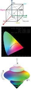
In traditional machine-vision systems, these color models or color spaces have been used to address specific market requirements. Dating back to the 16th century, numerous color models have been developed, although only a few have found universal acceptance (www.colorcube.com/articles/models/model.htm). These include color models based around the RGB cube; the CIE XYZ, CIE RGB, and CIE Lab; and the HSI color spaces (see Fig. 2). Because all of these color spaces are related, RGB data from color cameras can be converted using matrix transformations and represented within them.
For developers of image-processing software, this provides the tools needed to compute color differences within each model. In the RGB cube, for example, the three component values of color are plotted independently on x, y, and z axes, resulting in a color cube. Because each individual color within this color space can be identified by a single location within 3-D space, a color comparison between two different colors can be measured as a length of the vector between these points.
In the 1920s, color research by William Wright and John Guild resulted in the CIE 1931 chromaticity diagram that mathematically defined color space. In this color space, x and y represent two color coordinates. Because this model is based on the human perception of color, any two equal (x, y) coordinates will result in any two colors being perceived as the same. Although RGB coordinates can be transformed into this color coordinate system, it is important to note that the spectral response of a color camera will be limited by the number of reproducible colors. This concept is often illustrated by a triangular region within the diagram that illustrates the range of achievable colors.
Perceptually uniform
However, because this color space is not perceptually uniform, it is not particularly useful in determining the magnitude of the differences between colors. As a result, the CIE enhanced this color model, nonlinearly transforming the CIE 1931 XYZ space into a more perceptually normal opponent color space model—the 1976 CIE 1976 Lab color space. In this space, L represents the lightness, and a and b are color opponent dimensions that represent the color value between red/magenta and green and between yellow and blue, respectively.
To measure the difference between two colors, a Delta-E (dE) value that represents the distance between the two colors in three-dimensional space is used. Since a dE of 1.0 is the smallest color difference the human eye can perceive, this value provides an indication of the relative differences between different colors. These color models are often used by manufacturers of photospectrometers and developers of machine-vision systems to determine the differences between parts of different colors (see “Imaging systems tackle color measurement,”Vision Systems Design, August 2007).
Like many other color models, these different color spaces can be computed from RGB values (see “Manipulating colors in .NET,” http://69.10.233.10/KB/recipes/colorspace1.aspx). In machine-vision systems, however, changes in illumination levels can affect the perceived value of color and thus the returned RGB camera values. To compensate for this, many software vendors allow developers to compute color differences using the hue, saturation, and intensity (HSI) values of the image.
By ignoring the returned intensity value and computing the color using the hue and saturation components, any changes in brightness will be dramatically reduced. Matrox Imaging’s color tools (part of the Matrox Imaging Library, MIL), for example, include tools for color distance, projection, and matching that work with the RGB, HSI, and CIE Lab color spaces. The distance and projection tools are commonly used to set up subsequent analysis: The distance tool reveals the extent of color differences in and between images, while the projection tool separates features from an image based on their colors.
Recently, Orus Integration used these color tools in a system to sort blueberries according to their average hue, average brightness, size, and roundness (see “Systems Integrator gets the blues—the berries, that is,” www.matrox.com/imaging/en/press/feature/food/blueberry/).
Like Matrox’s MIL, EasyColor software from Euresys includes a set of optimized color-system transformation functions and color analysis functions, including RGB, XYZ, Lab, Luv, YUV, YIQ, and HSI. Separating the intensity component from saturation and hue allows a more intuitive interpretation of colors and is useful to segment colors while eliminating lighting effects. Also included in EasyColor are traditional color image-processing functions (such as Bayer pattern conversion and color balance correction) and color analysis functions that allow the developer to detect and classify color objects and defects.
Sapera Essential by DALSA also includes a color classifier that allows segmenting nonuniform color regions such as color textures. This is useful in food inspection where surfaces often appear as nonconstant color areas. Coupled with DALSA’s blob analysis tool, this makes the classifier an appropriate tool for color sorting and inspection.
Color differences
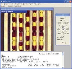
For system developers building color verification, sorting, and inspection systems, the choice of color model, although important, may not be as relevant as how precisely the system can measure these color differences. The differences are, of course, very useful if the purpose is to ensure the right color product is being produced, says Robert McConnell, president of WAY-2C. However, he says, there is a huge difference between color measurement and color-based recognition. Systems designed for one are not usually well suited for the other, particularly when the objects of interest are multicolored. Using train-by-show methods, WAY-2C software provides statistical classification, verification, and anomaly detection tools to differentiate object classes of interest (see Fig. 3).
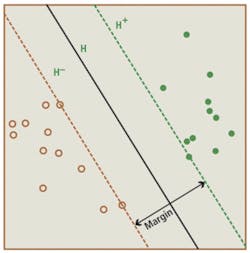
This type of supervised learning technique is also the basis for support vector machines (SVM), a method of classifying data as sets of vectors in a multidimensional vector space. After image data are classified in this way, the SVM generates a hyper-plane to maximize the margin between each data set. This technique is used in the Manto object-classification software from Stemmer Imaging for applications such as handwriting and license plate recognition (see “Support vector machines speed pattern recognition,”Vision Systems Design, September 2004).
More recently, this technique has been implemented in hardware by Paula Pingree, a senior engineer at the Jet Propulsion Laboratory of the California Institute of Technology, in an FPGA-based system designed for on-board classification of satellite image data (see “Developing FPGA Coprocessors for Performance-Accelerated Spacecraft Image Processing,”Xilinx Xcell Journal, Second Quarter 2008). In the system developed by Pingree, image data is streamed to the SVM, which performs the required SVM operation on the image, classifying pixel data by constructing a separating hyper-plane that maximizes the margin between the learned and raw image data (see Fig. 4). Pixel classifications such as snow, water, ice, land, cloud, or unclassified data are then written to an output file.
Despite the usefulness of different color models and methods, today’s color measurement and recognition systems still remain subject to the instability of the lighting, cameras, and frame grabbers or the use of unrepresentative training sets. As McConnell points out, the best way to ensure reliability is to test the system under conditions designed to be worse than those in the production environment.
Company Info
DALSA, Waterloo, ON, Canada
www.dalsa.com/mv
Euresys, Angleur, Belgium
www.euresys.com
Jet Propulsion Laboratory, CIT, Pasadena, CA, USA
www.caltech.edu
Matrox Imaging, Dorval, QC, Canada
www.matrox.com/imaging
Orus Integration, Boisbriand, QC, Canada
www.orusintegration.com
Sony Electronics, Tokyo, Japan
www.sony.com
Stemmer Imaging, Puchheim, Germany
www.stemmer-imaging.de
The Imaging Source, Bremen, Germany
www.theimagingsource.com
WAY2C, Hingham, MA, USA
www.way2c.com
