Simplifying Automotive Assembly
3-D vision-guided robotic system combines with LED lighting, laser line generators, contact sensors, and PLC to precisely place front ends
Winn Hardin, Contributing Editor
Automobiles may weigh several tons, and major subassemblies may weigh several hundred pounds. While lift-assist systems can help line workers cope with heavy assemblies, these systems cannot eliminate the dangers of human/machine interactions in tight work spaces or stress from repetitive motion. The result can lead to human errors that cost automobile makers financial losses on warranties and recalls.
This was the challenge facing Czech Republic-based ŠKODA AUTO during a recent retooling of production lines for the new model Superb and the launch of the new Yeti SUV line. The question arose: What is the best way to place and fix the front radiator/fan assembly to the two models of automobiles in a repeatable process, while maintaining the flexibility to adapt to future models or design changes?
The Yeti SUV model was launched in the spring of 2009; the ŠKODA Superb sedan has been in production since 2001. In 2009, ŠKODA added 10 cm of length to the car along with other design changes. Thus, the production lines for both models were ideal applications for automation and the requisite labor and quality improvements that come with robot assembly.
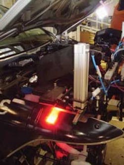
To meet this challenge, system integrator Neovision, in cooperation with Lipraco and M+W Process Automation, developed the FrontEnd vision-guided robotic system (see Fig. 1). It is based on the KUKA VKRC 360 robotic arm, guided by a combination of contact and noncontact sensors and two Point Grey Research Scorpion FireWire cameras with laser line illumination.
Neovision chose to combine low-cost contact sensors with high-precision 3-D machine vision to develop a simple robot guidance system that would provide the flexibility to adapt to future design changes and new models. By combining rough 3-D location data of the automotive frame with precision 3-D information from the vision system, FrontEnd can place the radiator assembly to within 1 mm accuracy (see video below).
Contact and contactless measurement
In the ŠKODA assembly plant in Kvasiny, vehicles travel down the assembly line on custom fixtures that accommodate the unique automotive frame. The fixtures are mounted to rails and pulled by a drive chain. While the custom fixture guarantees that the automotive frame will be seated to within a few dozen millimeters in the x,y-axis—as viewed by a robot-mounted camera system—the depth information or z-axis information varies based on the quality of the mechanical stop.
In either case, mounting the front radiator and fan assembly requires position tolerances of 1 mm to guarantee safe operation. Even using lift-assist technology, humans take considerably longer to align the assembly with the mounting holes on the automobile frame; in contrast, the FrontEnd robotic workcell can place and mount the assembly within a few seconds and well within design tolerances.
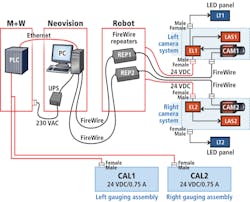
As the vehicle frame enters the FrontEnd assembly area, two Point Grey Research Scorpion SCOR-20SOM CCD cameras, illuminated by custom LED panels from Neovision, send a stream of images across the FireWire connection to a FireWire repeater, and then to the host PC, which runs side by side with a Siemens Simatic S7 PLC (see Fig. 2).
The images are fed at 15 frames/s at full resolution (1600 × 1200 pixels) into Neovision's C++-based image-processing software package, Neodyme, where edge detection and geometric pattern searches yield rough 3-D location data of the automotive frame. Once the frame is located within the target area, the vision system sends the information to the PLC, which stops the line for assembly and triggers the robot to start collecting a front end assembly from a nearby rack of parts (see Fig. 3).
Following a programmed path developed by robot specialist M+W Process Automation, the robot swings over to the parts rack and collects a radiator/fan assembly (front end assembly) using a custom actuator developed by Lipraco specifically for the front end assembly of that model. The robot then moves to the front of the automobile frame and roughly positions the front end assembly based on a combination of programmed robotic movements.
The robot eases the part forward and its movements are tracked by the PLC using a pair of contact sensors mounted on each side of the custom robot actuator that holds the front end assembly. After the contact sensors tell the PLC that the robot arm is in position to begin the assembly, the PLC sends a trigger across an Ethernet connection to the PC host running the FrontEnd machine-vision system.
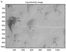
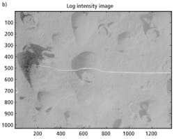
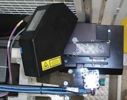
The vision system triggers the two Scorpion cameras to take a series of images, using both visible light, and images illuminated by a Coherent Lasiris SNF-701L-660T-10-45, 660-nm-thick laser line generator. The cameras, via the machine-vision host PC, trigger both lights based on OPC signals from the PLC. Using the cameras to trigger the lights rather than a separate I/O card in the PC allowed the Neovision designers to run fewer cables along the robotic arm, eliminating the need for costly rugged cables and a point of failure for the system (see Fig. 4).
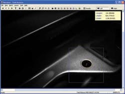
After aligning the white-light-illuminated images with images of the laser line, the Neodyme software running a Microsoft Windows XP environment uses pattern matching, edge detection, and triangulation algorithms to determine the exact position of the engine compartment, and by association, the screw holes that will hold the radiator/fan assembly. Once the automotive frame location is determined, the vision system returns offset values in all three axes to the Simatic PLC, which runs the robot. The robot then alters its programmed path based on the real location of the frame, and the PLC triggers pneumatic ratchets that fix the radiator/fan assembly to the frame.
"We used the Scorpion cameras because of our experience with Point Grey's equipment, the ability to quickly switch between different shutter and gain settings for consecutive images, and the camera's general purpose input/output [GPIO], which we used to switch on the LED lighting and to operate the lasers, eliminating the need for additional cables from the PC to these devices," explains Petr Palatka, managing director at Neovision (see Fig. 5).
"To accommodate different paint colors, the FrontEnd system automatically determines optimal exposure settings for both cameras based on images taken of each car," continues Palatka. "The car colors can vary from darkest blacks to shiny metallic silver finishes, so single exposure settings cannot cover the whole range of automobiles coming down the line.
"We have to determine the optimal exposure from several preassembly images, using various shutter and gain settings," he adds. "This has to be done as fast as possible because the entire measurement cannot take longer than 2 s. This approach based on 3-D measurement is reliable and more flexible than alternative, 1-D contactless sensors."
Images from the assembly operation are stored locally on the PC and then uploaded to a long-term, file-based database running elsewhere in the plant for later review by ŠKODA engineers as necessary. The car and front end placement are inspected one final time, during the mounting of the headlight lamps.
Company Info
Coherent
Santa Clara, CA, USA
www.coherent.com
KUKA Roboter
Augsburg, Germany
www.kuka.com
Lipraco
Mnichovo Hradiště, Czech Republic
www.lipraco.cz
M+W Process Automation
Prague, Czech Republic
www.processautomation.mwgroup.net/cz/
Neovision
Prague, Czech Republic
www.neovision.cz
Point Grey Research
Richmond, BC, Canada
www.ptgrey.com
Siemens
Nuremburg, Germany
www.siemens.com
ŠKODA
Mladá Boleslav, Czech Republic
www.skoda-auto.cz
