Tunable Optics
Andrew Wilson, Editor
Many of the optical systems used in machine-vision and image-processing systems are based on glass or plastic lenses. While some of these systems employ fixed-focal-length lenses, others require lenses where the focal length must be changed. In traditional mechanically based lens systems, this is accomplished by translating the optical elements within the lens against each other.
As the predominant method of focusing images for over a century, mechanical lens motion sharply contradicts the biological methods found in nature. By leveraging principles based on these methods, manufacturers are now developing different types of small deformable lenses that can be tuned over various focal distances. Because these lens systems can be miniaturized relatively easily, they are finding applications in smart machine-vision cameras, endoscopy systems, and cell phones.
Different engines
At present, many disparate technologies are being employed to perform autofocusing. These include devices based on electro-optical, electromechanical, thermo-optical, and acoustomechanical techniques. While electro-optical devices may incorporate electrowetting or liquid-crystal cells to perform this function, electromechanical techniques also use a number of different servomotors, MEMS micropumps, and piezoelectric devices to achieve lens deformation. Other emerging techniques employ heat and sound to achieve similar effects.
First demonstrated more than five years ago by both Philips Research and Varioptic, liquid lenses that use electrowetting technology perform autofocusing by employing a lens comprising two immiscible fluids of different refractive indexes. In both the Philips and Varioptic designs, these consist of an electrically conducting water solution and electrically nonconducting oil (see Fig. 1). The interface between these liquids then forms a natural diopter, due to the index difference of the two liquids.
To control the shape of the lens, an electric field is applied across the hydrophobic coating so that it becomes less hydrophobic—a process called electrowetting that results from an electrically induced change in surface tension. As a result, the aqueous solution begins to wet the sidewalls of the tube, altering the radius of curvature of the meniscus between the two fluids and thus the lens’ focal length. By increasing the electric field, the surface of the initially convex lens can be made completely flat or even concave. As a result it is possible to implement lenses that transition smoothly from being convergent to divergent and vice versa.
Liquid crystals are also being employed in other types of electro-optical adaptive lens designs to perform autofocusing. In the technique used by LensVector, for example, a control voltage is applied to dynamically change the rotation of molecules in a liquid-crystal cell to achieve a change in refractive index. In applying this voltage, the differential rotation of the liquid-crystal molecules from the center to the periphery of the element is changed, focusing light at the desired focal distance (see Fig. 2). By tuning this voltage, the differential rotation of molecules in the element results in a lens that can be focused from infinity to 10 cm.
Electro-mechanical designs
While electro-optical techniques are employed by Varioptic, Philips, and LensVector, other designs are being developed that use electromechanical techniques. Research on electroactive polymers (EAPs) at ETH Zurich by Manual Aschwanden has led to the development of an electrically focusable lens from Optotune. Rather than use two different types of liquids, the principle behind Optotune’s design is based on a dielectric elastomer actuator (DEA). Applying a voltage to two electrodes connected to either side of the DEA results in expansion of the polymer.
This principle can be used to form a lens based on the material that will then bend as the electric field is applied. Using this technique, Optotune has introduced its first product, the EL-10-30, which is claimed to be the world’s first focus tunable lens that exhibits a diameter greater than 5 mm. By applying an electrical control voltage of 0–5 V, the focal length of the lens can be tuned to any value between 15 and 50 mm.
Both Holochip and Rhevision rely on mechanically tunable liquid lenses. In their designs, the lens fluid is pumped into or out of the lens enclosure, and the lens membrane expands to form either a concave or convex shape to achieve focus or zoom (see Fig. 3). This approach, says Shin-Tson Wu of the University of Central Florida, relies on a transparent fluid that is encapsulated between a see-through, flexible membrane and a flat glass substrate.
When a tiny servomotor compresses a circular periphery seal that acts like an iris diaphragm, the shape of the membrane grows convex, modifying the fluidic lens’ focal length. To market the technology, UCF has signed a licensing agreement with Holochip that gives the company exclusive worldwide rights to Wu’s adaptive lens patents, including five US patents and numerous foreign applications (see “Adaptive lenses mimic the human eye,” Vision Systems Design, November 2007).
To deform this membrane, a number of different methods can be used. In a design proposed by Wu, this is accomplished by rotatable impellers that form part of the peripheral seal of the lens. When the impellers are rotated clockwise, this suppresses the liquid filled lens and the elastic membrane swells outward, forming a converging lens. Similarly, when the impellers are rotated counter-clockwise, a diverging lens is formed. Wu has also demonstrated a lens that uses a thin string attached to a servomotor to achieve this same effect.
Rhevision’s technology, spun out of the Optics Laboratory of the University of California–San Diego, uses similar principles, driving the lens with a MEMS micropump to achieve a tuning range of approximately 200 diopters or ten times the tuning range of the human eye.
Researchers at the Council for Scientific & Industrial Research and the Department of Microsystems Engineering (IMTEK) at the University of Freiburg have also developed a variation of this technology, using an adaptive silicon membrane driven by a piezoelectric actuator (see “Characterization of Adaptive Fluidic Silicone-membrane Lenses,” SMEOS 2009 Proceedings, ISBN 978-0-620-45648-7).
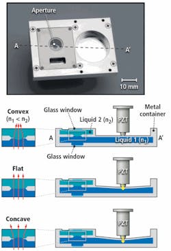
Piezoelectric actuators have also been used by Hiromasa Oku of the University of Tokyo in a similar design that uses a two-chamber approach to achieve the same effect (see Fig. 4). In the design, two immiscible liquids are located in two chambers connected by a circular hole. The liquid–liquid interface that is formed at the hole then acts as the aperture of the lens. Because of the different refractive indices of the two liquids, this interface operates as a refractive surface. The lower chamber is equipped with a deformable wall that is pushed by the piezoelectric actuator to change the volume of liquid in the upper chamber. By doing so, the curvature of the interface can be changed dynamically.
Heat and sound
While these remain the most widely publicized technologies, several researchers worldwide are developing other designs to perform such tasks. These include thermally tunable lenses and those that use high-frequency sound modulation to change the shape (and thus focus) of the lens.
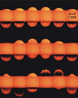
At Columbia University, Xian Huang and his colleagues have developed an array of thermally tunable microlenses comprised of polydimethylsiloxane (PDMS), a silicon-based organic polymer. To fabricate the microlens array, an indium tin oxide (ITO) thin film was first placed onto a glass substrate to form an array of microheaters and temperature sensors.
Spherically shaped cavities in the form of a PDMS sheet were then bonded to the substrate (see Fig. 5). By increasing the temperature of the microheaters below the PDMS lenses, the radius of curvature changes due to the thermal expansion of the PDMS causing a change in the lens’ focal length. By monitoring the changes in resistance of the ITO temperature sensors, the microlens temperatures and thus focal length can be measured.
While many methods for manipulating liquid lenses involve changing the size and shape of the area where the liquid contacts a surface, to bring an image into focus, Amir H. Hirsa at Rensselaer Polytechnic Institute is using an acousto-optical approach to focus his liquid-based lens. To achieve this, Hirsa’s method couples two droplets of water through a cylindrical hole. When exposed to certain frequencies of sound, the device exploits inertia and water’s natural surface tension and becomes an oscillator. Water droplets then resonate back and forth with the rate of oscillations determined by different sound frequencies.
By passing light through these droplets, the device is transformed into a miniature camera lens. As the water droplets move back and forth through the cylinder, the “lens” moves in and out of focus, depending on how close it is to the object. The images are then captured electronically, and software used to automatically edit out any unfocused frames, leaving only focused images.
FIGURE 6. By coupling two droplets of water through a cylindrical hole and exposing them to certain frequencies of sound, the device becomes an oscillator. Water droplets then resonate back and forth with the rate of oscillations determined by different sound frequencies. As water droplets move back and forth, the “lens” that is formed moves in and out of focus.
While such autofocus lenses have for a number of years been the subject of much research, they are now being deployed by companies developing smart cameras for machine vision. Indeed, autofocus lenses based on Varioptic’s electrowetting technology have already been employed in both the DataMan 100 and 200 series of image-based ID readers from Cognex and the QX Hawk barcode imager from Microscan. In future, it appears that, whichever technology is adopted, such self-adaptive lenses will be used in other applications, most notably cell phones and endoscopy systems where miniaturization is an important design consideration.
Company Info
Cognex
Natick, MA, USA
www.cognex.com
Columbia University
New York, NY, USA
www.columbia.edu
Council for Scientific & Industrial Research
Pretoria, South Africa
www.csir.co.za
ETH Zurich
Zurich, Switzerland
www.ethz.ch
Holochip
Albuquerque, NM, USA
www.holochip.com
LensVector
Mountain View, CA, USA
www.lensvector.com
Microscan
Renton, WA, USA
www.microscan.com
Optotune
Dübendorf, Switzerland
www.optotune.com
Philips Research
Eindhoven, the Netherlands
www.research.philips.com
Rensselaer Polytechnic Institute
Troy, NY, USA
www.eng.rpi.edu
Rhevision
San Diego, CA, USA
www.rhevision.com
University of California–San Diego
San Diego, CA, USA
www.ucsd.edu
University of Central Florida
Orlando, FL, USA
www.ucf.edu
University of Freiburg
Freiburg, Germany
www.uni-freiburg.de
University of Tokyo
Tokyo, Japan
www.u-tokyo.ac.jp
Varioptic
Lyon, France
www.varioptic.com
