Choosing a frame grabber for machine-vision applications
By Stephane Francois
Hundreds of frame grabbers are on the market to allow integration of digital and analog machine-vision cameras with host computers. Varying features make each one unique for a particular application. When evaluating frame grabbers for a specific application, developers must be aware of specific camera types (either digital or analog), the sensor types they use (area or linescan), their systems requirements, and the cost of peripherals.
DIGITAL FRAME GRABBERS
To guarantee low latency between image acquisition and processing, frame grabbers with digital camera interfaces such as Camera Link cameras are often used, especially in high-speed semiconductor applications. The Camera Link standard’s Full configuration allows a maximum of 680 Mbytes/s (64-bit at 85 MHz), currently the highest bandwidth on the market.
High-speed applications can also benefit from onboard tap reordering that can be accomplished with many frame grabbers. This removes the burden of recomposing an entire image from complex multitap cameras (several simultaneous data channels) from the host computer. Other features, such as the recently available power-over-Camera Link standard, offer simpler integration (a single cable for power and data) of compatible Camera Link cameras when this feature is available on the frame grabber.
ANALOG FRAME GRABBERS
Even with established standards such as RS-170, NTSC, CCIR, and PAL, great differences exist among analog frame grabbers. Differences appear through jitter, digization quality, and color separation, all of which affect image quality. However, because it is difficult to compare frame grabbers from datasheet specifications, many OEMs benchmark several models before making a selection.
Some analog frame grabbers can handle multiple cameras either through multiple analog interfaces or multiplexing techniques, thus reducing the number of frame grabbers used in multicamera systems. When multiplexing video on a frame grabber, the resynchronization time required with each switching reduces the total frame rate. In the case of a multiple simultaneous input configuration, onboard memory will guarantee that images are transferred without loss of data.
AREA-ARRAY CAMERAS
Today’s frame grabbers commonly offer onboard FPGAs to perform neighborhood operations such as convolution, off-loading the task from the host PC. This allows functions such as Bayer color interpolation and dead-pixel management to be performed directly on the frame grabber. While some cameras offer Bayer interpolation internally, most frame grabbers can also handle the task. Several ways exist to interpolate camera data when a Bayer pattern is used. The most simple linear interpolation gives relatively poor image quality; an intermediate quality method is bilinear interpolation; the highest quality is obtained by nonlinear interpolation.
Similarly, dead-pixel management can be used to correct the images and reconstruct or interpret neighborhood pixel values. Each pixel is compared to its neighbors, and if there is a very high- or low-intensity pixel, a dead pixel may exist and a new value is computed using kernel-based algorithms. Although the host computer can perform these operations internally, it requires substantial processing power.
Frame grabbers that support linescan cameras are mostly used in applications requiring a high level of synchronization between the movement of objects on a conveyor and image acquisition. To interface to such conveyors, frame grabbers usually provide interfaces to TTL, RS-644, optocouplers, and pulse dividers (to adjust the encoder pulse-per-line ratio) and support for bidirectional encoders (where opposing movements are necessary). Linescan cameras can be difficult to integrate in cases where lines are generated constantly. Large quantities of data are generated and could create data-transfer issues-some frame grabbers may lose lines of image data.
Frame grabbers can also interface to trilinear linescan color cameras. These cameras use a sensor comprising three lines, each covered with a color filter-typically red, green, and blue. Here, the pixel information of each color line does not represent the same physical location in space, so it is necessary to realign each color. For example, if the camera has red, green, and blue filters, in that order, the green channel has to be delayed by one line and the blue by two to match the red channel. This spatial registration can be easily performed on a frame grabber, off-loading the PC of this function.
The ease of integrating a frame grabber into a vision system is determined by how simple it is to synchronize image acquisition with external events controlled using TTL, RS-644/LVDS, and optocouplers. The most general use of I/Os is for triggers: an external signal from a sensor or programmable logic device indicates that an image must be captured. In many applications, external lighting is required, and the frame grabber offers dedicated signal lines to synchronize strobe lighting with the camera’s integration period. Most frame grabbers offer additional digital I/Os that can be used for other types of acquisition or synchronization.
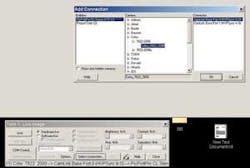
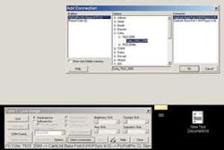
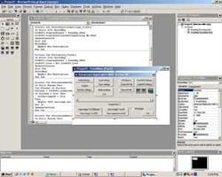
All frame-grabber manufacturers provide software with their hardware. The software usually consists of a driver for the operating system to recognize the hardware and a software development kit that allows the control of the frame grabber under common software development tools such as C/C++, VB, .NET, and Delphi (see Figs. 1 and 2). It is also common for frame-grabber manufacturers to provide image-processing software as a package.
Over the years, the unit cost of frame grabbers has decreased because of the lower cost of components used to build them and increased competition. However, unit cost is not the only consideration when selecting a frame grabber. Development time and maintenance can become critical when developers encounter problems with image acquisition. To limit potential issues during development, developers should work with a company that provides a range of frame grabbers and acquisition devices.
Frame grabbers offer more than the transfer of image data into a host computer. Frame grabbers can enhance the features of digital cameras and speed image processing tasks. They act as a technological buffer between cameras and continually changing computer products. Of course, simple applications such as data acquisition can run with less sophisticated frame grabbers, but at the expense of having the PC perform all the image-processing operations.
Stephane Francois is executive vice president of Leutron Vision, Burlington, MA, USA; www.leutron.com.


