Sensors expand IR imaging range
Improvement in MCT detectors, camera design, and signal processing enable new long-wavelength IR R&D applications.
By Christopher J. Alicandro
A growing number of infrared (IR) photovoltaic 2-D focal-plane-array (FPA) detectors are becoming commercially available for integration into high-performance IR cameras. Sensor technologies include indium gallium arsenide (InGaAs), indium antimonide (InSb), mercury cadmium telluride (MCT), and quantum-well IR photodetector (QWIP). In addition, microbolometers also have closed the performance gap with photovoltaic detectors, although significant performance differences remain. Proper selection of sensor technology depends on application and systems requirements.
Over the past 15 years, InSb FPAs have reached commercial maturity and are now available in formats over 1K × 1K. These FPAs feature mid-wavelength IR (MWIR) spectral responsivity and >90% quantum efficiency and result in IR imaging systems with thermal sensitivities under 20 mK (see “MWIR and acoustics reveal subsurface defects,” p. 33). While a significant number of military electro-optical platforms have transitioned from scanned long-wavelength IR (LWIR) “common module” based sensors to MWIR InSb-based sensor engines, they are more commonly found on airborne and marine platforms where the 3-5-μm bandwidth works well in typical atmospheric conditions. On the other hand, ground-based IR imaging platforms continue to rely on LWIR systems because of their performance under anticipated battlefield conditions.
Previously, systems designed for LWIR imaging have had several options: integrated advanced linear arrays with time delay integration (TDI), microbolometers, and QWIP FPAs. While these technologies deliver good performance, there are some limitations for R&D applications. TDI-based systems, for example, lack the ability to perform simultaneous (snap shot) integration, variable frame rate, and variable integration settings. Microbolometers offer wide spectral response (7-14 µm) but exhibit lower thermal sensitivity (typically >50 mK), require fast optical designs (~f/1.0-1.5), and have long thermal time constants that limit performance speed to 60 frames/s. QWIP-based systems offer higher thermal sensitivity but have low quantum efficiency.
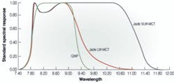
Despite the higher cost of MCT-based LWIR systems compared to low-cost microbolometer systems, as well as QWIP-based systems, IR imaging systems based on MCT LWIR detectors have several important advantages. Recent advances in MCT FPA fabrication have led to the commercial availability of MCT-based IR imaging systems with long-wavelength spectral responsivity, good uniformity, higher operability (>98%), and broader spectral responses. Currently available LWIR MCT arrays provide spectral response from 7.7 to 9.5 µm, and extended response (beyond 11 μm) devices are being delivered in limited quantities (see Fig. 1).
LWIR ADVANTAGES
MCT-based IR imaging systems offer several key advantages over other sensors for certain applications. Many applications require imaging in the LWIR spectral band, including spectroscopy, laser-beam profiling, target signature analysis, and phenomenology. Related LWIR imaging systems must have spectral response around 10 µm and high interband sensitivity.
In addition, a high-performance LWIR system offers a very broad-dynamic-range capability. Specifically, this is important in those applications in which the object of interest spans a very wide temperature range, such as the test firing of a solid rocket booster (see photos on p. 31).
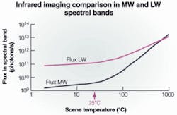
This extended intrascene dynamic range would not be possible with an MWIR system. The performance of the MCT LWIR system is explained by comparing the flux in the LWIR band with that in the MWIR band. As calculated from Planck’s curve, the distribution of flux due to objects at widely varying temperatures is smaller in the LWIR band than the MWIR band when observing a scene having the same object temperature range.
In other words, a LWIR imaging system can image and measure ambient temperature objects with high sensitivity and resolution while imaging extremely hot objects (that is, >2000 K). Imaging wide temperature ranges with an MWIR system would have significant challenges because when the system is adjusted so that the detector does not saturate as a result of the energy from the high-temperature object (by optical attenuation or short integration times), the result is poor sensitivity for imaging at background temperatures (see Fig. 2).
A LWIR imaging system is not only suitable for high-intrascene-dynamic-range applications, but is also uniquely suited for high-contrast imaging when the scene flux is quite small. For example, consider the application of IR imaging of cold objects. These objects have very little IR radiation. However, an MCT-based LWIR imaging system has the ability to adequately measure and distinguish the radiation from objects at temperatures down to -100°C. In addition, it has been shown that the full object temperature range can be imaged with one detector integration time.
LWIR CAMERA DESIGN
The value of LWIR technology comes not simply from the sensor/detector, but equally-if not more importantly-in the camera design, which must take advantage of all of the performance attributes of such a performance sensor. Deriving the value begins with the analog/digital circuitry. It is now possible to create an extremely deep dynamic range of 14 bits to best take advantage of the inherent detector dynamic range-this is a significant improvement over previous 8- and 12-bit systems.
In addition, the cameras themselves can include significant on-board signal processing to provide usable data directly from the camera head itself. Systems today have internal memory that allows the user to store nonuniformity and bad-pixel replacement algorithms without the use of an external computer or separate digital processor. The user can then choose whether to capture corrected or raw data. This “one box” approach allows a smaller footprint, less cabling, and significantly lower power requirements.
Because of innovations in DSP technology, ultrafast cameras (>250 full frames/s) can invoke “multi-integration time” (multi-IT mode) features and can store these multiple integration time corrections internally. Certain applications, ranging from printed-circuit-board analysis to ballistics testing require very wide thermal dynamic ranges, which may not be possible with a single integration time. A multi-IT mode will allow the user to cycle through integration times at the fastest rate that the camera can produce.
For example, if the camera has three integration times to cover a wide-scene temperature, the camera will cycle through integration times at full frame rates. That is, if the camera is running at 240 frames/s, the first frame will be at the first integration time, the second frame will be at the second integration time, the third will be at the third integration time, and so on. The system will effectively generate three sequences, three frames apart, each at 80 frames/s using the three integration times. There is also image processing available that will “recompose” these individual three sequences into one complete sequence making a pixel by pixel determination as to which integration time should be used, further increasing the dynamic range.
In the age of very-high-speed digital thermal imaging, it is possible to simultaneously capture high-speed digital video while streaming analog video. To do this, the cameras incorporate a video frame buffer, which allows both the possibility of simultaneous high-speed digital video and standard RS-170 (or CCIR) analog output. With higher-performance MCT IR detectors combined with state-of-the-art camera design and signal processing, end users can exploit the technology of thermal imaging in ways that were not previously possible.
Christopher J. Alicandro is director of sales for infrared products at Electrophysiscs, Fairfield, NJ, USA; www.electrophysics.com.
MWIR and acoustics reveal subsurface defects
Ultrasound excited thermography (UET) is a nondestructive-testing and examination technology that has been developed in a cooperative venture between CEDIP Infrared Systems (Croissy Beaubourg, France; www.cedip-infrared.com), Enhanced Defect Visualisation (Edevis; Stuttgart, Germany; www.edevis.de), and the Institute for Polymer Testing and Polymer Science at the University of Stuttgart (Stuttgart, Germany; www.zfp.uni-stuttgart.de). Edevis has been commercializing UET testing and analysis systems for the manufacturing industry over the past few years.
“UET is the interaction of acoustic and thermal waves,” says Alexander Dillenz, managing director of Edevis. “We use acoustic waves from a sonic generator to inspect subsurface material boundaries. Upon ultrasonic excitation, the friction heats up the subject material. The heat travels to the sample’s surface, generating infrared radiation, which we measure with a vision system based on CEDIP’s IR detectors and optical systems and our customized software.”
The technique detects mechanical hysteresis that can be caused by cracks, delaminations, poor bonding, or other material weaknesses. It can rapidly inspect areas as large as 0.5 × 0.5 m and detect cracks independent of their orientation. Subsurface flaws can be found, thus providing considerable advantages over traditional and more-expensive techniques such as color-penetration tests and x-ray computed tomography.
The acoustic waves are launched by an ultrasound transducer into the whole volume of the test specimen, where they are reflected until they disappear-preferentially in defects-and generate heat. These defects can be visualised by an IR camera that provides an image of heat flow caused by distinctive hot spots inside the test specimen.
High-frequency sonic excitation generates heat efficiently, since many hysteresis cycles are performed per second, rapidly producing a dissipation image with an excellent signal-to-noise ratio. Consequently, measurements can be performed at the surface within a few seconds. The ultrasonic generator can be adjusted both in frequency and amplitude; depending on the size and type of the target material, the typical frequency range is 15-25 kHz
According to Pierre Potet, managing director of CEDIP, the sensors are based on InSb or MCT, and the system uses a Jade MWIR camera operating in the 3-5-µm range. These cameras use a focal-plane array capable of detecting less than 20 mK of temperature change. The frame rate can be up to 250 Hz in full image mode.
Typically, the camera lens has a 25-mm focal length. The image-management system uses an LVDS-based frame grabber. The camera currently has an RS-422 interface, but Edevis is working on a future version to be based on either Camera Link or USB. For real-time image processing, Edevis has designed its own software based on C++. Dillenz says it is more or less standard, but there is an extra interface for Simatic Step 7, the control software from Siemens (Munich, Germany, www.siemens.com) for automating inspection on manufacturing lines.
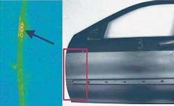
UET is changing the process of nondestructive testing and inspection of products on a manufacturing line by cutting costs and improving capabilities. The latest UET system can check the conditions inside metal, carbon fiber, and other polymer products, as well as check whether an adhesive joint is working properly in, for example, the glued joints between automobile parts (see photo).
Adhesive bonding is an established joining technique in vehicle construction. Modern lightweight design, safety, and modular concepts require improved rigidity, increased energy-absorption capacity, and fatigue strength. Adhesive-bonded joints, of which there are typically more than 100 m in modern automobiles, raise the issue of construction safety and must be inspected during the production process.
-Matthew Peach, European Contributing Editor


