Optimizing motion-control-system design
Choosing the right PC-based motion-control system requires evaluating motion controllers, software, amplifiers, motors, and positioning hardware.
By Andrew Wilson, Editor
At the heart of many automated manufacturing systems lie sophisticated motion-control systems that incorporate positioning systems, motors, amplifiers, and computer-based controllers. Although pneumatic and hydraulic actuators are used in high-power systems that manipulate heavy loads, many of today’s automated systems use electro-mechanical systems that incorporate computer-controlled linear or rotary motors.
In choosing the proper combination of components to develop a computer-controlled motion-based system, the design engineer must weigh many parameters. These include the types and weight of the load that must be moved, different types of stages and motors that can effectively move the object, which drive amplifiers interface to such motors, and how to control all of these elements using PC-based software.
With more than 3000 motor/drive combinations available, this integration problem may at first seem daunting. However, the process can be simplified using a bottom-up approach. In developing a motion-control system, one of the first considerations is the type of stage to use. This can be a linear, rotary, or specialized hexapod stage that can move in six axes (x, y, z and roll, pitch, and yaw). While individual linear stages can be combined to form x-y and x-y-z stages, often manufacturers offer preconfigured x-y and x-y-z stages or build them to meet a specific travel length.
One of the most important factors in determining which type of stage to use is the effect of different loads on the stage. “Different loads will affect the performance of the stage,” says Rahul Kulkarni, product manager of industrial data acquisition and controls at National Instruments (NI). “Using loads that are close to the maximum will often cause the stage to perform differently than with smaller loads. Also, when stages are stacked, the weight of the stages must be considered as part of the load carried by the lowest stage,” he says.
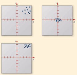
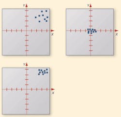
It is also essential to determine the minimum incremental motion or resolution required. This is the smallest distance the stage can move. After determining this, it is important to consider both the repeatability and accuracy of the stage. While linear-positioning accuracy provides a measure of how closely the motion matches a specific command, repeatability measures the extent to which successive attempts to move to a specific location varies in position (see Fig. 1).
Slide technologies
Motion-control-system developers can choose from several slide technologies, each of which has inherent advantages and disadvantages. The most common slides are dovetail, ball-bearing, and crossed-roller-bearing stages. Though they represent a low-cost alternative, dovetail slides often are inappropriate for high-precision applications because of the high friction associated with them. Ball-bearing-based stages eliminate this problem by replacing the friction of sliding motion with that of rolling motion. But because ball bearings make contact with the slide rails, these stages are limited in the amount of load they can carry. By replacing the balls with steel rollers, crossed-roller-bearing stages support larger loads at the expense of higher friction.
Various technologies, including lead or ball screws, belts, or rack-and-pinion technology, can be used to move the stage. Lead- or ball-screw drives are perhaps the most common way to convert rotary motion from stepper or servomotors to linear motion. Lead screws differ from ball screws because they slide, rather than roll. Ball screws, on the other hand, have one or more ball-bearing arrangements interspaced between a screw shaft and nut. As the screw or nut is rotated, the balls roll in helical grooves formed by the threads.
To move stages based on lead, ball screw, belt, or rack-and-pinion technology, either servo or stepper motors can be used. Generally less expensive than servomotors, stepper motors are permanent magnetic motors that developers can increment under computer control and that hold their position once stationary. They are most useful in low-speed applications where short, rapid repetitive motion is usually not a requirement. Servomotors require an encoder feedback loop so that computer-based controls can determine the position of the motor. These motors are often used in applications that require high torque and speed where greater shaft power can be delivered.
To overcome the limitations of the backlash, wear, and maintenance associated with lead, ball screw, belt, and rack-and-pinion driven motion control and positioning systems, linear drives can be used. These offer a novel way of driving particular types of stages using a variation of the ac servomotor called the linear induction motor. Although more expensive than screw-driven systems, linear-driven systems possess the speed and lower inertia that make them more suitable in equipment that requires long travel lengths. Replacing conventional ball screws and gears with direct drives-servo linear motors or torque motors-suppresses elasticity and hysteresis, while bandwidth, overall precision, and resolution are increased. When these motors are used, mechanical transmission maintenance and operating costs are reduced, and machine productivity is increased.
Motors and drives
Vendors including Aerotech, Copperhill Technologies, and Galil Motion Control have developed computer-based on-line support to assist in the selection of the best stage/motion/drive combination. Aerotech’s ServoSizer motor sizing workbook (available at ftp://www.aerotech.com/filedownloads/motor_sizing_worksheet) has engineers enter specific data, such as load, force, acceleration, and cycle time, to guide their choice of the company’s motor/amplifier combination range. Similarly, Galil’s MotionCode consists of a variety of motion-control solutions, each providing step-by-step procedures for guiding engineers in the design, development, and integration of motion applications. Available at www.galilmc.com/motioncode.html, the toolkit offers six MotionCode solutions, each of which details the procedure for implementing a Galil controller into a particular type of machine.
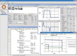
Copperhill’s more sophisticated VisualSizer-Online, released in May 2005, automatically determines the correct electrical motor and drive/inverter, according to specific servo-application specifications (see Fig. 2). Using the software, engineers can set up mechanical systems that use components such as lead screws, timing belts, gearboxes, and electrical motors and drives/inverters to calculate the torque, speed, and inertia requirements of a specific application. The software has a database containing thousands of motor/drive combinations from manufacturers such as Baldor Electric, Danfoss, GE Fanuc, Schneider Electric, and Siemens.
To properly power these motors, the appropriate drive amplifiers must be chosen. When interfaced to a computer-based controller, the drive amplifiers can be programmed to translate the low-voltage reference signals from the controller into high-energy signals to provide motor voltage and current. In some cases, manufacturers combine the functions of both computer-based controllers and drive amplifiers into a single unit.
Stepper motors are driven by digital pulses rather than a continuously applied voltage. These pulses translate to a number of shaft revolutions, with each revolution requiring a given number of pulses. Each pulse equals one rotary increment, or step, which represents a portion of one rotation. Because each count represents movement achieved, there is often no need to incorporate any feedback systems in the stepper motor, as is the case with servomotors. However, developers can use encoders with these types of motors to reduce motor slip effects. To drive these motors, the drive amplifier accepts clock pulses and direction signals from a host controller and translates these to phase currents that drive the motor in full step, half step, and microstep configurations.
Similarly, servomotor controllers can be used to convert signals from computer-based controllers and power ac- and dc-based servomotor drives. Because servomotors use encoder-based feedback to provide positional accuracy and velocity to the computer-based controller, developers must tune them after they attach the load to the drive, so the controller can obtain an optimal system response. The most common type of these control loops is referred to as the proportional integral derivative control loop, which is an integral software component of many computer-based motion-control software packages.
Powering the drive
After selecting the type of stage, motor, and feedback to use, system designers can choose from numerous drive amplifier controllers for both servo- and stepper motors that can drive single or multiple axes. Manufacturers such as Advanced Motion Controls offer helpful information about choosing servo drive amplifiers. The company’s Selection Guide helps the designer understand the load torque, inertia, and velocity of the system, as well as calculate the current and voltage necessary to obtain the required velocity and torque and select an amplifier or drive based on motor type. Available at www.a-m-c.com/selection.htm, the Selection Guide can help determine the appropriate drive amplifier parameters and products from the company’s products.
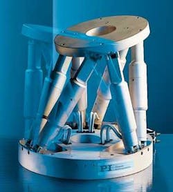
To ease the task of developing a motion-control system, many manufacturers, including Danaher Precision Systems, Micos, National Aperture, Parker Bayside Motion Group, Polytec PI, Primatics, Prior Scientific, and Suruga Seiki, provide integrated stages that combine slides, motor controllers, and amplifiers. These stages are offered in configurations that include linear, x-y, x-y-z, rotary, and hexapod versions (see Fig. 3).
PC-based control
Once specific stages are selected, integrators must decide how to control these stages. Although many of today’s applications use PC-based controllers, these stages can also be controlled using VME, VXI, PC-104, and stand-alone networked controllers. One of the most important parameters is the servo update rate, a measurement of how fast the control loop within the system can be closed.
While today’s DSP-based motion controllers feature servo update rates of up to 30 kHz and are suitable for many applications, high-precision motion-control applications with servo update rates as fast as 200 kHz require machine builders to design their own motion controllers on a custom PCB. Not only is the development expensive in terms of time and cost, custom systems can be inflexible and unable to accommodate variations in the motion-control algorithms at run time.
“Applications that need such a high level of precision and flexibility include wafer-processing machines in the semiconductor industry or in-line vehicle sequencing reconfigurable-at-run-time assembly lines for the automotive industry,” says Kulkarni of National Instruments. Because of this, NI has developed its reconfigurable I/O technology, which, when coupled with NI SoftMotion software, helps system integrators develop high-precision FPGA-based systems. “In addition,” he says, “machine builders can use the NI SoftMotion Development Module to implement multiaxis coordinated motion control with NI LabVIEW on plug-in M Series DAQ devices and systems using NI CompactRIO and Compact FieldPoint programmable automation controllers.”
For many motion-control applications, PC-based controllers do provide an ideal solution. What is perhaps less important than the number of axes each board can support, or the number of analog or digital I/O triggers available with such products, is the software support each vendor offers. While many controllers deliver blended motion trajectory control and fully coordinated circular, linear, and point-to-point control, the application programming interfaces (APIs) developers use to support them make maximum use of the Windows programming environment.
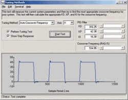
To program its PCI, ISA, PC-104, VME, and CompactPCI controllers, for example, Galil offers several graphical user interfaces. These include its ActiveX Toolkit that can create an operator interface for Galil controllers with Visual Basic or other software that uses ActiveX custom controls. Other companies such as CamSoft, Entivity, and Micro Digital also support Galil’s controllers with menu-driven Windows-based software (see Fig. 4).
With NI Motion Assistant, designers can implement a motion-control application in an interactive 3-D environment and convert it into C code for any C compiler, or into NI LabVIEW virtual instruments. NI Motion Assistant also uses a smart-contouring functionality with an API that can be called from C, Visual Basic, or LabVIEW. It also includes easy trapezoidal or S-curve velocity profile implementation, and teach pendant for easy prototyping.
Companies such as Motionsoft are looking to make motion-card-independent motion-control software. As a state logic and icon-based motion sequence programming tool, the company’s Motionsoft package eliminates the need to program in any control card native code and its associated language, reducing sequence development time. Designed to program many different motion-control cards, the software frees the developer from an understanding of the programming language syntax for each card that is programmed.
Although the software currently only supports the PMAC1, PMAC2, and Mini-PMAC1 from Delta Tau, Galil’s DMC1500, and the SMC2000 controllers from Yaskawa Electric America, future versions will support controllers from ACSTech 80, Compumotor, Motion Engineering, Kollmorgen, Pro-Dex, and others.
As the machine-vision industry continues to integrate cameras, processors, and lighting into more intelligent products, motion-control vendors are following a more integrated path to their customers through company acquisitions and alliances and integrated intelligent motor and controller products from companies such as Animatics and AllMotion. These alliances and new technologies will reduce integrated motion-control system development, lowering the cost and shortening the time to market for finished systems.
Top 10 motion-control Web sites
- “Accuracy in Positioning Systems” by Kevin McCarthy, NEAT www.neat.com/techinfo/pdf/accuracy.pdf
- “Video training web-casts” by Jacob Tal, Galil Motion Control www.galilmc.com/training/jacobvideoconfirm.html
- “Description of lead-screw technology” by Tom Solon, Kerk Motion Products www.kerkmotion.com/pdf/lead-screw-technology.pdf
- “Configuring a motion-control system” by National Instruments staffzone.ni.com/devzone/conceptd.nsf/
webmain/922C29061D5F384F86256ED3004CF069 - “Generate motion control from CAD drawings” by John Mazurkiewicz, Baldor Electric Company www.baldor.com/news/success_stories.asp?id=308
- “What is a servo?” by Advanced Motion Controls staff www.a-m-c.com/what_is_a_servo.htm
- “Anorad Product Videos-watch machines in motion” by Anorad staff www.rockwellautomation.com/anorad/literature/prod_videos.html
- “Investigating Servo Architectures-Pros and Cons” by WorldServo staff www.worldservo.com/html/arc.htm
- “Introduction to step motor systems” by Anaheim Automation staff www.anaheimautomation.com/intro.htm
- “Amplifier and motor technologies” by Copley Controls staff www.copleycontrols.com/motion/technologies
Company Info
| ACSTech 80, Migdal Ha-Emek, Israel www.acs-tech80.com | Advanced Motion Controls, Camarillo, CA, USA www.a-m-c.com |
| Aerotech, Pittsburg, PA, USA www.aerotech.com | AllMotion, San Jose, CA, USA www.allmotion.com |
| Anaheim Automation, Anaheim, CA, USA www.anaheimautomation.com | Animatics, Santa Clara, CA, USA animatics.com |
| Anorad, Shirley, NY, USA www.rockwellauto mation.com/anorad | Baldor Electric, Fort Smith, AR, USA www.baldor.com |
| CamSoft, Wildomar, CA, USA www.camsoftcorp.com | Compumotor, Rohnert Park, CA, USA www.compumotor.com |
| Copley Controls, Canton, MA, USA www.copleycontrols.com | Copperhill Technologies, Amherst, MA, USA www.copperhilltech.com |
| Danaher Precision Systems, Wood Dale, IL, USA www.neat.com | Danfoss, Nordborg, Denmark www.danfoss.com |
| Delta Tau, Chatsworth, CA, USA www.deltatau.com | Entivity, Ann Arbor, MI, USA www.entivity.com |
| Etel, Schaumburg, IL, USA www.etel.ch | Galil Motion Control, Rocklin, CA, USA www.galilmc.com |
| GE Fanuc, Charlottesville, VA, USA www.gefanuc.com | Kerk Motion Products, Hollis, NH, USA www.kerkmotion.com |
| Kollmorgen, Wood Dale, IL, USA www.kollmorgen.com | Micos, Eschbach, Germany www.micos.ws |
| Micro Digital, Costa Mesa, CA, USA www.smxinfo.com | Motion Engineering, Santa Barbara, CA, USA www.motioneng.com |
| Motionsoft, East Providence, RI, USA www.motionsoft.com | National Aperture, Salem, NH, USA www.nationalaperture.com |
| National Instruments, Austin, TX, USA www.ni.com | Parker Bayside Motion Group, Port Washington, NY, USA www.bmgnet.com |
| PI (Physik Instrumente), Auburn, MA, USA www.pi-usa.us | Primatics, Tangent, OR, USA www.primatics.com |
| Prior Scientific, Rockland, MA, USA www.prior.com | Pro-Dex, Beaverton, OR, USA www.omsmotion.com |
| Schneider Electric, Rueil-Malmaison, France www.schneider-electric.com | Siemens, Munich, Germany www.siemens.com |
| Suruga Seiki, Shizouka, Japan www.suruga-g.co.jp | WorldServo, www.worldservo.com |
| Yaskawa Electric America, Waukegan, IL, USA www.yaskawa.com |
