Infrared cameras vie for multispectral applications
To extract a greater quantity of information from captured images, camera and systems vendors are turning to multispectral cameras.
By Andrew Wilson, Editor
Today, the demand for low-cost visible sensors has grown to a point where visible 4k × 1 linescan and 2k × 2k area-array-based cameras are now commonplace. CCDs or CMOS sensors in machine-vision cameras provide a number of specific benefits to the developers of machine-vision and image-processing systems. Just as these cameras are becoming commodity items, however, vendors of detectors, cameras, and systems are exploring ways to add value to their cameras while providing additional features to their customers.
One of the ways of accomplishing this is to develop systems that image objects in more than one frequency spectrum. For example, while visible light cameras use the 400-700-nm spectrum to image objects, ultraviolet imagers, operating in the 10-400-nm frequency band can provide additional information, such as scratches or surface contamination of an object (seeVision Systems Design, July 2006, p. 25) .
Infrared (IR) cameras operating from the short-wavelength-infrared (SWIR) spectrum (0.7 µm) to the long-wavelength IR (LWIR) spectrum (to 15 µm) are also useful in detecting specific characteristics of objects that may be difficult to image in the visible spectrum. Using a combination of one or more frequency spectrums, in so-called multispectral systems, can be especially useful in applications such as food- inspection, medical, and military imaging systems, where a combination of visible and invisible data must be captured.
Unfortunately for the system developer, terms such as “multispectral” are often misunderstood. While many microbolometer-based IR cameras do image scenes across the 0.5-15-µm spectrum, for example, their sensitivity is somewhat less than specialized cameras based on technologies such as InGaAs, MCT, or QWIPs. More properly, the term multispectral refers to the ability of an imaging system to detect electromagnetic energy in at least two or more individual spectral bands, such as visible and IR.
“For many applications measuring different spectral bands including near-IR provides more specific information about the sample than simply RGB image data,” says Jens Michael Carstensen, technical director of Videometer. “The spectral reflectance of some wavelengths and absence of others is a specific characteristic of many materials that can be applied to characterize materials by using only relevant material from the analysis to find defects and foreign matter” (see Fig. 1).
While some may imagine capturing multispectral data from both IR and visible wavelengths implies the use of multiple detectors, the opposite is true. SUI, Goodrich (formerly Sensors Unlimited Inc.) and FLIR (formerly Indigo Systems), for example, both offer sensors and cameras that operate in the visible and near-IR spectrum.
“In commercial applications, visible-SWIR cameras can assist in machine vision as well as in hyperspectral imaging. The same array can allow multiple “colors” across two wavelength bands to be imaged by one camera. This simplifies the optical system and the processing required to analyze and compare two camera images,” saysDoug Malchow, a research engineer with SUI, Goodrich. The use of InGaAs in its SU640SDV Vis-1.7RTInGaAs SWIR camera, for example, allows detection of images across the 400-1700-nm spectrum. With both a 14-bit digital Camera Link and RS-170 output, the camera can be used with PC-based cameras or broadcast-compatible monitors.
Though SUI, Goodrich says it was the first company to develop such technology, FLIR also uses InGaAs in its Alpha near-IR sensor head, a 320 × 256-pixel focal plane array (FPA) that is sensitive across the 900-1700-nm waveband.
Active denial
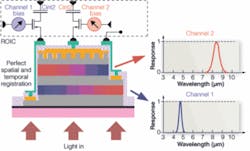
While these sensors do exhibit multispectral responses, other methods can offer similar results. One of the most promising is the development of “dual-color” QWIP devices. At last year’s SPIE Defense and Security Symposium, Qmagiq showed such a “dual-color” IR camera based on a 320 × 256 dual-color or dual-wavelength detector array (seeVision Systems Design, June 2005, p. 15).
Because the device can detect IR images in both the 4-5-μm medium-wavelength IR (MWIR) and 8-9-μm LWIR spectral bands simultaneously, this makes the device especially useful in military applications that previously required two different IR detectors. The device in the camera consists of two layers of InGaAs/GaAs/AlGaAs quantum-well stacks. In the voltage-readout circuitry, a different channel bias is applied to each detector layer, allowing IR detection at dual wavelengths (see Fig. 2).
“One application driving the development of these products is the military’s joint service active denial system that uses millimeter-wave energy to stop, deter, and turn back any advancing adversary from relatively long range. This system is expected to save lives by providing a way to stop individuals without causing injury before a deadly confrontation develops,” says George Williams of Voxtel Technology. His company has used Qmagiq’s sensor to develop a dual-band radiometer (DBR) to measure absolute temperature measurements at long ranges.
“To achieve absolute skin-temperature measurements, the DBR was built to achieve ±1°C accuracy for which the use of Qmagiq’s QWIP FPA was key. This dual-band QWIP was integrated with the FLIR ISC006 ROIC customized for dual-band QWIPs and packaged in an integrated Dewar cooler assembly. With a custom camera controller, built by Voxtel, the complete system consisting of a laser rangefinder, telescope, and associated electronics was packaged in a 0.5m x 0.5m x 0.16m enclosure. Operational field tests are now planned to demonstrate the technology readiness level of the system.
While company’s such as Voxtel are targeting military applications with dual-band cameras, others are looking at developing integrated cameras for machine-vision applications. “In principle,” says Alka Swanson, chief operating officer at Princeton Lightwave, one camera can acquire images in the visible spectrum while another acquires images in the IR.
Inside the body
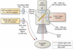
Several recently developed systems illustrate just how this can be done. At Beth Israel Deaconess Medical Center, for example, John Frangioni and his colleagues have developed a near-IR fluorescence imaging system to allow surgeons to visualize optical and near-IR fluorescence images simultaneously (see Fig. 3 on p. 70).
“By maintaining separation of the visible [color] and near-IR fluorescent light, it is possible to simultaneously acquire visible anatomical images and near-IR florescence images that show the vessel, nerve, and tumor location and overlay the two in real time. To ensure correct registration of the images, light emanating from the surgical field was split into color video and near-IR fluorescence emission components using a dichroic mirror mounted in a standard Nikon TE300 microscope filter cube. For recording of color images, a Hitachi model HV-D27 three-chip CCD camera was connected to a PCI-1411 S-Video frame grabber from National Instruments (NI),” says Frangioni.
For recording of near-IR fluorescence images, an Orca-ER interline CCD camera from Hamamatsu was connected to NI’s PCI-1422 frame grabber. All control software was written in LabView Version 6.1 and IMAQ Vision 6.1. “Although the color video camera was expensive, it uses a highly sensitive 1/2-in. three-chip design and has excellent color reproduction. The near-IR camera has reasonable QE at 800 nm and has an interlined output. Although a GaAs-based detector may have achieved a higher QE, the Orca offers an excellent price/performance ratio and is easily interfaced to LabView,” Frangioni continues.
Measuring vegetation
Using a similar filter cube approach, Bryan Shaw at the Center for Imaging Science at Rochester Institute of Technology has recently built a dual-wavelength camera specifically for remote-sensing applications. Instead of using visible and IR cameras, however, Shaw’s camera uses off-the-shelf CCDs that have Wratten filters to filter specific frequencies of light. In this way, the normalized difference vegetation index (NDVI), a measurement of the increase in reflectance between the red (650 nm) and near-IR (750 nm) spectral signature of vegetation, can be measured.
“At these two wavelengths,” he says, “a sharp contrast is seen between healthy vegetation and the soil background. A high NDVI value indicates complete and healthy coverage of the observed land, whereas a low NDVI value represents sparsely vegetated areas.”
In developing a dual-band camera to measure this parameter, Wratten filters #25 and #87 were used for the “red” and “infrared” cameras, respectively. While #25 removes all blue in IR, #87 removes all visible light. To calibrate both imagers, an Air Force Test Target was imaged with each camera and then using the register function in of the ENVI software package from ITT Visual Information Solutions both images could be registered.“
Assessing vegetables
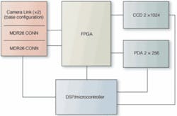
Many dual-band inspections, however, require that the two images be automatically spatially and temporally registered-data from the same resolved spot on an object must be collected for both bands at the same time,” says Princeton Lightwave’s Swanson. For customers is the food-inspection industry, the company has developed a dual-band linescan camera that uses two independent sensors optically coupled to allow simultaneous imaging in both the visible (400-900 nm) and IR (1000-1700 nm) wavelengths (see Fig. 4).
While visible sensing is provided by a 2k × 1 CCD, IR is detected by a 512 × 1 element InGaAs array. Pixels are optically aligned, enabling the simultaneous imaging of both spectrums at a 4:1 resolution. Each sensor provides two analog output streams that are processed using correlated double sampling, dark level correction, and analog gain.
Finally, the streams are converted to 12-bit digital data and buffered into dual-port RAM for synchronization and further digital processing. Two independent Camera Link interfaces are provided for transferring processed image data from the camera.
These cameras, developed for military, remote-sensing, medical, and machine-vision markets, command a premium in today’s image-processing and machine-vision applications markets. The added benefit they provide, however, is allowing sensor, camera, and systems suppliers to add greater value to their products, while avoiding commodity markets such as low-cost security and surveillance. Slowly, as the demand for more sophisticated sensors rises, multispectral imaging will become more commonplace.
High-speed IR camera captures images without blur
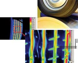
Infrared (IR) cameras can image fast-moving objects and measure the temperature of any point on an object without the errors associated with motion blur. One application is in the study of the thermal characteristics of tires in motion. Using a high-speed IR camera to observe tires running on a dynamometer at speeds in excess of 150 mph, researchers can capture detailed temperature data during dynamic testing to simulate turning and braking loads (see Fig. 1).
To optimize imaging performance for this application and minimize motion blur requires the careful selection of camera exposure time, frame rate, and spectral band. This involves calculations that depend on the linear velocity of the tire, the desired spot-size resolution, the anticipated temperature range, and the desired thermal sensitivity.
Normal operating temperatures for tires are within the ambient operating specification of a tire, plus a factor for the load-induced heating of the tire under a wide range of load and speed conditions. For my company’s testing, we assumed that the maximum temperature a tire would be about 70°C. Given the uniform material properties of a tire, it is assumed that the temperature resolution or sensitivity required for proper analysis of the tire under various test conditions will be <0.25°C.
Based on a 16-in. wheel and 4-in. sidewall, the circumference of a tire will be 3.1416 × 24 (16 + 4 + 4) = 75.3 in. Assuming a speed of 60 mph, the linear velocity is 1056 in. (26,822 mm)/s. Assuming the resolution desired is 0.2 in. (5 mm) ±15% for acceptable motion displacement, you can calculate the exposure time necessary. You need to integrate the sensor during the period of time it takes the tire to move 0.03 in. (0.2 × 15%). The integration time is determined to be 28.4 μs.
Because the tire temperature is relatively cool, an LWIR camera will perform much better than an MWIR camera. From Planck’s Law, as a target temperature increases, the peak wavelength associated with that temperature shifts toward shorter wavelengths. An LWIR system has its peak sensitivity around room temperature, while an MWIR system has its peak sensitivity around 400°C. Therefore, an LWIR system can better achieve the short exposure and sensitivity performance objectives.
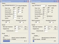
Using a Planck’s calculator function one can determine the specific well capacity of the focal-plane array at a given integration time and a given target temperature. At an integration period of 28 μs and an object temperature of 80°C, the LWIR detector’s charge capacitor fills to 34%, while an MWIR camera will only fill the charge capacitor to 6%. (The MWIR camera will perform better for higher-temperature testing.) For this particular application, in simple terms there are many more photons in the LWIR than in the MWIR, and more photons will mean better signal (see Fig. 2).
In addition, high-performance thermal-imaging systems can be synchronized with rapidly occurring events. In this tire-testing example, it is possible to have an optical encoder on the rotating tire that allows precise position location. The TTL signal generated by the optical encoder can be fed into the thermal-imaging system to trigger the integration time of the camera. The result is that every time the encoder sends the pulse, the camera integrates and creates an image. This allows a real-time stop image sequence to be created via software.
High-speed infrared imaging can provide important thermal data for rapidly moving objects. For the example of a high-speed tire testing application, an LWIR camera proved superior, resulting in sub-125-mK performance at an integration time of about 30 μs, with object blur smaller than 1 mm. This level of performance is important in understanding the thermal properties of the tire pattern.
Chris Alicandro
Electrophysics, Fairfield, NJ, USA
www.electrophysics.com


