NIWeek highlights progress in technology
The meeting emphasizes the close link between developments in software and progress in machine vision and automation.
By Andrew Wilson, Editor
Held from August 8 to 10 in Austin, TX, USA, the National Instruments (NI) annual trade show and conference proved to be more than just a celebration of the 30 years the company has been in business and the 20-year history of its LabView software. While there were, of course, the usual new product introductions, the keynote speeches, conference, and trade show provided a showcase where attendees could learn about the latest technology trends and applications and see demonstrations of machine-vision systems in action.
In his keynote address, James Truchard, NI president, spoke of the need for an even greater level of abstraction to further simplify graphically oriented programming languages; the promise of asynchronous, heterogenous multiprocessing; and, of course, how LabView would be addressing these issues. This theme was taken up by a number of speakers who described features of the company’s latest software incarnation, LabView 8.20: The 20th Anniversary Edition.
A different class
Stephen Mercer, a staff software engineer, described the advantages of object-oriented development and how the concept had been incorporated into the package. In his presentation, Mercer showed how graphical-object-oriented programming could generate more modular, maintainable, and flexible code.
Object-oriented applications are made up of a set of related functions and variables called “classes” that consist of both data and “methods” that perform an action on a class. By defining a new class based on the methods and properties of another class, this so-called “inheritance” allows a developer to reuse code across multiple applications.
“With the introduction of LabView classes in 8.20,” says Mercer, “the software becomes a fully object-oriented programming language that supports data encapsulation, class inheritance, and dynamic dispatching.” Using 8.20, developers can organize their virtual instruments (VIs) to create new data types specific to an application.
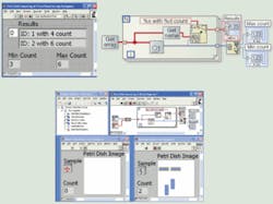
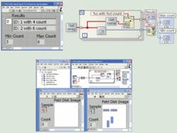
To highlight the usefulness of this object-oriented approach, Mercer showed how he had developed a simple imaging system designed to capture, process, and display images from Petri dishes. In this example, the original VI takes in an array of images, counts how many bacteria are in the dish, and reports the results (see Fig. 1).
“Now suppose the developers are asked to create a similar program to count red blood cells,” Mercer explains. “The applications are nearly identical, except that the image will have different information in it, and the function that detects the shape of the bacterial encapsulated in some deep sub-VI needs to be replaced with one that detects red blood cells.”
In the past, the entire file hierarchy would need to be duplicated and amended so that new image data type could flow through all the sub-VIs. Using object-oriented programming, however, this task becomes easier since LabView classes can be used. Developing two classes for bacteria and blood cells allows both data and methods (in this case different image types and the sub-VIs needed to process them) to be encapsulated in the two different classes. These sub-VIs that process the different image data types are then automatically dispatched at run time with the correct data type.
By introducing object-oriented concepts to its graphical programming language, the software lets developers produce modular, flexible, and reusable code. Better still, using such constructions in conjunction with the company’s Vision Builder 3.0 will allow even more sophisticated machine-vision systems to be built.
NeW SCRIPTS
To allow developers to add pre-existing text-based code to their LabView-based applications, NI has added MathScript, a math-oriented, textual programming to LabView. Compatible with Matlab from The MathWorks, MathScript can be used in conjunction with LabView’s graphical dataflow programming language to develop algorithms, explore signal-processing concepts, and analyze results.
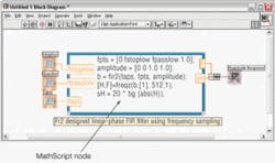
At the heart of MathScript is a text-based programming language that abstracts the complexity of tasks related to signal processing, analysis, and math. The MathScript Node offers an intuitive means of combining graphical and textual code within LabView (see Fig. 2). One of the major benefits of this is that developers need not bother purchasing Matlab to run m-files. LabView is all that is required. Of course, one of the major differences is that while Matlab is an interpreted software package, LabView is a compiled graphical programming language.
“Unfortunately ‘interpretation’ and ‘compilation’ are themselves relative terms,” says Darren Schmidt of the LabView Math and Signal Processing Group and NI’s technical lead in the Numerical Mathematics Consortium. “In MatLab, all code written in m-files is interpreted. In interpreted environments, you use techniques such as type inferencing and resource caching, in addition to calling compiled code for built-in core functionality.
“Regardless of these ‘tricks,’ it’s impossible to overcome certain execution hurdles. In LabView, VIs are compiled,” says Schmidt. “This facilitates better performance but does require data types to be known at runtime, thus disallowing the ‘interpretation’ at execution. LabView does supply some data types (for example, variants, dynamic data) that can store different types of data at runtime but the operators applied to that data must be known (and linked in) before a VI runs.”
NI’s MathScript is a scripting language and also refers to the execution environment in which the language is used. While the language is textual, its functionality is built on top of LabView so it has the potential to provide the performance of a compiled environment. In fact, when you run a script in MathScript you are actually executing LabView code.
In addition, it is designed with the interpreted capabilities customers desire when prototyping algorithms in textual math environments. So, it is both interpreted and compiled. Because it has interpreted components, a script in MathScript is likely to run slower than an equivalent G-code implementation. To what degree this occurs heavily depends on how much ‘interpretation’ is being done in the script, and that typically revolves around data. If you can operate on matrices as a whole, performance is very good if not excellent and can approach pure G speed. However, if you disassemble matrices, operate on the smaller parts over and over again, and then put them back together, lots of interpretation is done and performance suffers.
“The moral of this interpreted story is that if you do lots of tiny things in an interpreted environment,” says Schmidt, “expect at least one big result-the execution time!” Because MathScript plays well with LabView, it is easy to design a hybrid application that integrates both graphical and textual programming (or compiled and interpreted execution) seamlessly. That is a unique and very powerful proposition for engineers needing to solve real-world problems.
To incorporate MathScript within LabView, named inputs and outputs on the MathScript Node border specify data transfer between the graphical LabView dataflow programming and the textual MathScript code. Figure 2 shows variable inputs on the left side of the MathScript Node named fstoplow, fpasslow, and taps that input these parameters to the m-file script. The MathScript Node contains output variables, F and sH, that transfer the array-based result to LabView’s graphical code.
In addition to being compatible with MatLab, LabView 8.20 can incorporate algorithms from other packages, including Maplesoft Maple, Mathsoft Mathcad, and Scilab. With NI’s Simulation Interface Toolkit, developer’s can use simulation models developed in The MathWorks’ Simulink software environment in LabView for real-time control prototyping and hardware-in-the-loop testing. Additionally, LabView’s 8.20 Simulation Module can be used with third-party models from Dynasim and Plexim.
Make it move
One of the benefits of NI’s motion controllers is their ease of integration with the company’s data-acquisition and vision subsystems, allowing a single vendor solution for building automated measurement and control applications. The similar APIs of the various programs modules within LabView allow applications involving vision, data acquisition, and motion control to be developed more quickly.
Using NI Motion Assistant 2.0 software for prototyping single- and multiaxis motion-control systems, for example, motion profiles can be imported from CAD and drafting programs in the DXF file format. These profiles can then be incorporated in NI’s CompactRIO programmable automation controllers or to generate code for PCI/PXI plug-in motion controllers.
After saving a motion profile as a DXF file in a CAD or drafting program such as AutoCAD or SolidWorks, engineers can use NI Motion Assistant 2.0 to instantly import the profile and save motion-specific commands in an XML file format without writing additional code. They can then dynamically import this XML file into LabView or C applications with NI motion hardware.
In addition, Motion Assistant 2.0 features a graphical, point-and-click interface with 3-D visualization capabilities for creating motion-control applications using stepper, servo, and piezoactuators. NI offers a free 30-day trial version of the software at www.ni.com/motion.
Hardware, too
Of course, this year’s NIWeek would not have been complete without the numerous hardware product introductions that the company rolled out to complement the new software features of LabView (see “New product introductions at a glance,” p. 48). As well as NI’s products, the show floor was replete with new product introductions from third-party vendors.
For its part, Sony announced that the company’s XCI-SX1 Smart Camera was now shipped with NI Vision Builder for Automated Inspection (AI) software. Using Vision Builder, engineers can configure more than 100 machine-vision tools, including pattern matching, optical character recognition, and particle analysis and can communicate triggering and inspection results directly to industrial devices over the camera’s digital I/O and Ethernet protocols.
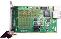
Similar to a PC, the camera is equipped with an x86-compatible processor running XPe operating system and costs $3975. Vision Builder AI software is an extra $1495. Just as the hardware offerings from NI reflected a renewed interest in PXI Express, so too did add-in boards from Conduant and PLDApplications (see Fig. 3).
Conduant, a developer of direct-to-disk, long-duration recording and playback systems, introduced its StreamStor PXIe-416 PXI-based data recording system. The 3U PXI-Express card with four-lane endpoint connectivity to host PXI-Express backplanes can record at 600 Mbytes/s sustained for more than 3 1/2 hours. Supporting more than 8 Tbytes of storage attached as four separate StreamStor DM4 data modules with a total of sixteen 500-Gbyte disk drives, the StreamStor PXIe-416 records and/or plays back as peer-to-peer transfers within PXI-Express, eliminating contention with non-real-time elements of the computer system.
PLD Applications (PLDA) showed its latest PXIe XpressLite development kit interfaced to a 48-frames/s A202k Base Camera Link camera from Basler. Based on Altera’s Cyclone II FPGA, the development kit offers the resources necessary to capture an image, perform any necessary pipelined image-processing functions on captured images, and pass the results to a host CPU. The PXIe IP controller is delivered preinstalled in the FPGA on the PXIe CY2 and handles PXIe bus communication. The IP controller is supplied with a reference design and simulation scripts used to illustrate how the IP functions and can be modified to initialize and configure the camera, dialogue with the camera, and establish a link with the PC.
Putting it together
Perhaps the most interesting part of NIWeek were the contributions made by many of the NI’s Alliance partners and third-party developers who described how they had used the company’s hardware and software to solve specific machine-vision-related tasks. Although these papers were not presented individually, they provided a glimpse of how vision systems were being deployed in numerous applications including quality control, product sorting, and measurement.
“Plywood-veneer moisture content can be very high if the wood is cut from a tree’s outer sapwood layer instead of its inner heartwood core,” says Rob Taylor of LightWave Computing. “To maintain a good glue bond between plywood veneers and maximize veneer strength, plant operators must dry each sheet within a tightly controlled moisture range. A wet section of veneer in an otherwise dry heartwood sheet can make the sheet blow out inside the steam press, causing delamination of the plywood and resulting in lost production and increased costs.”
Because of this, Westmill Machine Automation collaborated with LightWave Computing to develop the software for a vision-based moisture-sensing system. In this system, a pulsed LED linear light source penetrates the veneer on the conveyor. A linescan CCD camera detects the light intensity that passes through each sheet, and the image is digitized with a frame grabber embedded in a PXI-8187 controller.
Depending on the veneer species and thickness, plant operators can use LabView to adjust the LED brightness on the fly and obtain the maximum dynamic range from the CCD camera. Because captured image intensity correlates closely with the localized veneer-moisture content, the data can be used to control digital I/O modules that activate PLCs to sort the panels into different bins.
Plastic and chips
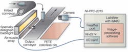
Developing an automated sorting system for clear transparent PETE plastic with machine-vision technology at a rate of 40 parts/s was the challenge faced by Averna Technologies. “In this application,” says Sébastien Parent, “plastic objects fall at around 9 ft/s from a conveyor running at 4.5 ft/s and must be sorted using an array of air nozzles (see Fig. 4). Using a field of view 2.8 in. high and 28 in. long with a resolution of 0.044 in./pixel, 40 images of 64 × 640 pixels have to be processed. At the end of each process, rules are applied to determine which air nozzle to open. To reach the image-acquisition rate with the selected field of view, a CMOS color camera from PixeLINK was used in a windowing mode to increase the frame rate of the sensor.
Vision Builder was used as the prototyping and functionality-testing platform and then translated into LabView. After image acquisition, two HIS thresholds were applied on the acquired color image. The first extracts only white information, the second extracts color information. Once the information is extracted from the initial image, the two thresholded images are separated in 20 equal areas of 64 × 32 pixels (2.8 ×1.4 in.). The system performs a pixel count for each of these nozzle areas, and comparison-logic software determines which air valves are activated.
Sorting of a different kind was the focus of a paper from Jeff Long of AutomationWorks. “To accommodate tight process step tolerances in the semiconductor industry, wafers must be presorted into narrow categories based upon electrical and mechanical parametric values after they are sawn from an ingot before processing,” he says. To presort these wafers, GigaMat Technologies called upon Long to speed the development of its latest wafer sorting system-the 200TRT.
“Wafer alignment is performed by rotating the wafer in the field of view of a linescan camera,” says Long. “By synchronizing camera scans with chuck rotation, a 6-Mpixel image of the wafer edge is composed in a single revolution, which takes about 1 s. Because camera scans are synchronized with chuck position, they are independent of chuck velocity and can be acquired during chuck acceleration and deceleration to speed throughput. Wafer features are identified from image data using LabView tools. The wafer is then rotated and indexed to bring it into alignment for the system’s measurement station.”
Four USB bus-powered M Series data-acquisition devices
USB bus-powered data-acquisition products feature multifunction M Series capabilities for applications such as data logging, portable measurements, and lab experiments. The USB-6210, USB-6211, USB-6215, and USB-6218 devices are available with up to 32 16-bit, 250-kS/s analog input channels and up to two 16-bit, 250-kS/s analog output channels. The devices feature up to eight digital input and output channels and two 32-bit counter/timers. They ship with NI-DAQmx driver and measurement services software.
USB Data-acquisition system
CompactDAQ system offers an eight-slot chassis that accepts I/O modules that can measure up to 256 channels of electrical, physical, mechanical, and acoustic signals in a single system. All module slots are hot-swappable and auto-detectable and offer up to 2300-V rms isolation. The system delivers four dedicated USB signal streams for synchronous analog and digital I/O for sound and vibration, mixed-signal test, and data-logging applications. DAQmx measurement services software includes an open API for LabVIEW, C/C++, Visual Basic 6, and Microsoft Visual Studio .NET and the DAQ Assistant, a wizard utility that automatically generates LabVIEW code.
PXI Digitizer
NI PXI-5152 digitizer/oscilloscope provides 1-GS/s sampling rate on two simultaneous channels or 2 GS/s on one channel. The module features a 300-MHz bandwidth and input ranges from 100 mV to 10 V with 50-Ω and 1-MΩ software-selectable input impedance. With an onboard memory of up to 512 Mbytes, the module operates with LabVIEW, C, Microsoft C++, and Visual Basic.
PXI Chassis and controller
PXI-1033 PXI chassis features five peripheral slots and includes a host card to control the system from either a desktop or laptop and a cable. With the integrated MXI-Express controller, 110-Mbyte/s sustained throughput to the host PC can be achieved.
PXI Express DAQ modules
PXIe-6259 and NI PXIe-6251 M Series DAQ modules have up to 32 analog channels with 16-bit, 1.25-MS/s sampling speed; up to four analog output channels with 16 bit, 2.8-MS/s update rates; and 10-MHz digital I/O up to 32 lines. The modules feature NI-STC 2 system controller, NI-PGIA 2 amplifier, and NI-MCal calibration technology.
PCI Express controllers
To control PXI systems using the PCI Express bus in PCs, NI has announced two PCI Express add-in cards. The NI PXIe-PCIe8371/2 x4 provides 1-Gbyte/s bandwidth and features a cabled PCI Express link from a PC to one PXI Express chassis. The PXIe-PCIe8372 has two cabled PCI Express links to simultaneously control two PXI Express chassis for a higher channel count. For PXI system control, the PXIe-8105 x4 dual-core embedded controller offers up to 1-Gbyte/s system bandwidth, 1-Gbyte /s slot bandwidth and features a 2.0 GHz dual core Intel processor. Finally, the NI PXIe-8351 x4 dual-core rack-mount controller is a 1U PXI Express controller that uses a cabled PCI Express connection to a PXI Express system. The NI PXIe-8351 controller features a 3.0-GHz dual-core Pentium processor, and dual Gigabit Ethernet and SATA II RAID-0 hard-drive configurations.
