Accessories complement Camera Link capabilities
Repeaters and fiberoptic extenders are increasing the flexibility of Camera Link-based systems.
By Andrew Wilson, Editor
While new standards can bring benefits to system integrators, they can also prove lucrative for manufacturers of products and peripherals that incorporate them. One example of this is the incorporation of the Universal Serial Bus (USB) by manufacturers of PDAs, laptops, and desktop peripherals. With more than 2 billion connections worldwide, USB can now be found on products including keyboards, video cameras, flashcard readers, hubs, and switches.
An external serial bus, USB now supports multiple devices and data rates up to 480 Mbits/s and allows peripheral devices to be either self- or bus-powered. Manufacturers now offer numerous adapters, converters, repeaters, and extenders with which to augment USB-based systems.
While the USB interface is now prevalent on most PC manufacturers, the five-year-old Camera Link interface has gained similar acceptance among manufacturers building cameras and frame grabbers for high-speed machine-vision applications. Unlike USB, the Camera Link standard is a point-to-point deterministic interface that uses a parallel-to-serial transmitter at the camera and a serial-to-parallel receiver at the frame grabber.
While Camera Link uses Channel Link transceivers for video data, strobes, and clock signals, an additional low-voltage-differential-signal (LVDS) receiver and driver provides a bidirectional asynchronous communications channel. Four additional LVDS pairs are used for general-purpose camera-control signals. The Camera Link’s Full configuration allows camera data to be transferred at rates as high as 680 Mbytes/s using transceivers running at 85 MHz.
Cables and connectors
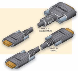
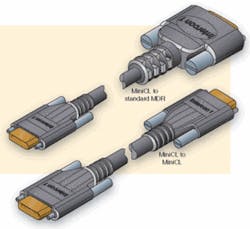
Using the Camera Link interface, camera and frame-grabber manufactures now offer a standard way to interface cameras to computers using standard Camera Link cables and connectors. At present, Carrio Cabling, OCP Group, Technical Cable Concepts, and TKM Technologies all offer the cables. As well as manufacturing standard MDR-26 connectors for these cables, 3M and Honda (through its distributor Components Express) are now delivering cables and connectors for the smaller pin-for-pin compatible mini-Camera Link connector. Since the mini-Camera Link connector is pin-for-pin compatible with the larger MDR-26 connector, adaptors such as the MCLCP from companies such as Intercon 1 can interface frame grabbers and cameras using the larger connector with newer products that may incorporate the smaller form-factor connector (see Fig. 1).
FIGURE 1. Since the mini-Camera Link connector is pin-for-pin compatible with the larger MDR-26 connector, adaptors such as the MCLCP from companies such as Intercon 1 can interface frame grabbers and cameras using the larger connector with newer products that may incorporate the smaller form-factor connector.
With the imminent announcement of a “Power over Camera Link” proposal from the Automated Imaging Association, cable vendors will be presented with another opportunity to add to their product portfolios (see Vision Systems Design, February 2006, p. 23).
In and out
Manufacturers of peripheral products for Camera Link also offer a number of converters, repeaters, and extenders. By using converters, system developers can convert the output of LVDS, RS-422, and DVI-based cameras and vice versa. To extend the approximate 10-m reach of Camera Link cables, repeaters can boost the output from signals between camera and frame grabbers. For further distances, numerous companies now offer fiber-based extenders that claim to extend this distance up to 10 km (Click here to download a PDF of the Repeaters and Amplifiers Extending Camera Link Capabilities table).
To perform functions with the Camera Link interface where very high speed imaging is not required, such as industrial measurement and medical research, Imperx’s Adapt-A-Link converters allow system developers to leverage their investment in existing cameras or frame grabbers with dissimilar Digital Visual Interface (DVI), Camera Link, LVDS, or RS-422 interfaces. To convert from LVDS, RS-422, or DVI standards to Camera Link and from Camera Link to LVDS and RS-422, the company offers nine individual stand-alone converters.
Interestingly, the company is one of the first to support conversion from DVI to Base Camera Link at an 82.5-MHz clock rate. DVI, which was created by the Digital Display Working Group, uses transition-minimized differential signaling to transfer data in either single or dual link modes at bandwidths of 165 or 330 MHz. To interface this standard to Camera Link, Imperx’s DVI-CL uses the digital DVI’s digital interface standard (DVI-D) to support image resolutions from SVGA (640 × 480) to UXGL (1600 × 1200) into a Dual Base Camera Link output at 85 MHz. Like the USB standard, numerous DVI adapters, switches, and converters can be readily purchased from companies such as RAM Electronics Industries.
Other manufacturers, such as Pleora Technologies, allow digital Camera Link and LVDS cameras to be interfaced over networking protocols such as Gigabit Ethernet. While the company’s digital iPORT IP products currently interface to more than 100 Camera Link Base and Medium cameras, the company also offers support for LVDS and GigE cameras, as well as Base and Medium Camera Link configurations. To allow analog cameras based on standards such as RS-170, CCIR, NTSC, PAL, and SECAM, Pleora’s ANL analog series of iPORT devices support both progressive-scan cameras at rates of 30 frames/s or higher in partial scanning mode.
Repeating signals
According to the Camera Link specification, the length between camera and frame grabbers is limited to 10 m. In some applications, however, this may not be enough, and a number of repeaters are available to extend this length by an additional 10 m. In cases where camera-to-frame-grabber distances must be extended further, fiberoptic extenders are required. Although more expensive than 10-m repeaters, these peripherals can extend camera/computer interfaces by hundreds of meters.
Connecting one Camera Link cable from the camera to the repeater and the second from the repeater to the frame grabber provides a 20-m reach between camera and frame grabber using a pair of standard 10-m Camera Link cables. At present, most of the repeaters from companies such as Mikrotron, Photonfocus, and Vivid Engineering support the Base Camera Link configuration, although several repeaters and cables may be cascaded to support greater distances.
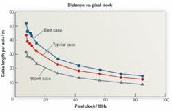
In choosing a repeater, system integrators should be aware of the clock rate of their cameras and frame grabbers. While Mikrotron’s B562 Camera Link repeater and Vivid Engineering’s 66-MHz CLR-101 and CLR-101A repeaters, for example, can be used with Base Camera Link configurations to clock rates up to 66 MHz, Photonfocus’ Digipeater CLB26 is specified at differing clock frequencies. At 20 MHz, cable distances can be as long as 20 m either side of the repeater, providing a 40-m camera reach. At 66 MHz, the maximum cable length is specified as 10 m either side (see Fig. 2).
null
FIGURE 2. Photonfocus Digipeater CLB26 is specified at differing clock frequencies. At 20 MHz, cable distances can be as long as 20 m either side of the repeater, providing a 40-m camera reach. At 66 MHz, the maximum cable length is specified as 10 m either side.
To interface to Medium and Full configuration Camera Link systems, system integrators can use multiple repeaters. Although one might imagine that this may introduce synchronization problems between transmitted and received data each of the channels, this is not the case. Because a phase-locked transmit clock is transmitted in parallel with the data streams over an LVDS link, using multiple repeaters to transmit image data introduces no such synchronization problems.
Fiber adds distance
In many aerospace and military applications, data may need to be transmitted much further than 20 m. In such cases, system integrators must consider using fiber-based extenders. These peripherals can extend the distance between camera and frame grabber often up to several kilometers and are also useful in harsh environments such as weapons testing and steel mills, where EMF from external sources may corrupt the transmitted data.
In choosing a fiber extender to suit a particular application, system integrators must consider a number of factors. These include the clock rate of the camera and frame grabber, whether Base, Medium, or Full mode is used, if any I/O is provided, the distance required between camera and frame grabber, and the type of fiber and connectors that the extender manufacturer supplies.
Unfortunately, many of the specifications of these products are quite confusing. Because the Channel Link devices used in Camera Link each offer 24 bits of image data and four control lines (for a total of 28 bits), three such devices are required to implement the full specification. While the Base mode uses one Channel Link transmitter/receiver pair to transmit up to 28 data bits, the Full configuration can theoretically support a theoretical 72 bits of video data at speeds of up to 85 MHz.
In specifying their Camera Link compatibility, vendors of fiber extenders often just specify the image data bits used. In its opticlink CL series of extenders, for example, Arvoo specifies a number of options including Base 16-bit, Base 24-bit, dual Base 24-bit, Medium 48-bit, and Full 64-bit interfaces running at 66 MHz. Likewise, Phrontier Technologies describes its dual Base/Medium Camera Link Fiber extender as using six 8-bit taps running at 66 MHz.
While many extenders support data rates of 66 MHz, both the CFL-3 and CFL-4 from Logical Solutions support Base, Medium, and Full camera configurations at rates up to 85 MHz. “This,” says John Thomas, vice president of sales, “allows cameras such as Mikrotron’s 85-MHz MC1310, Atmel’s AViiVA M4 CL 6007, and Basler’s 504KC to be supported at full data rates.”
To transmit Camera Link data, manufacturers of fiber extenders offer both multimode and single-mode interfaces using either subscriber connectors (SCs) or the smaller Lucent Connector (LC) style. While single-mode fiber typically reaches distances of around 10 km and has high information-carrying capacity, low attenuation, and low fiber cost, multimode-based systems that reach on the order of several hundred meters can be implemented less expensively. Recognizing this, companies such as Logical Solutions offer a number of different LC, ST, and SC connectors including and fiber options for use with their products.
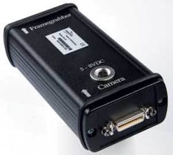
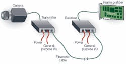
In implementing a fiber-based system, it is often necessary to also transmit image data and I/O signals. To do this, Logical Solutions and Stride Technologies provide bidirectional general-purpose I/O in addition to the Camera Link connection (see Fig. 3). These can be used, for example, to remotely control illuminators, motorized lenses, or extend the serial port of the host PC.
null
