Telecentric lenses make precise measurements
Telecentric lenses add an extra level of precision to machine-vision systems.
By Andrew Wilson, Editor
In many machine-vision systems, such as those used in semiconductor inspection, precise repeatable measurements must be made consistently. To ensure this occurs, system developers must turn to more expensive optical systems based on telecentric lenses with which to image these parts. Many of the reasons for choosing telecentric lenses emerge from the limitations of more conventional lens systems.
For example, should an object move even slightly within the depth of field of a conventional lens system, there will be an associated magnification change. In the past, magnification changes due to object displacement were calibrated by means of an additional camera or a depth sensor tracking the distance between the lens and the object. The use of a telecentric lens can substantially reduce or even eliminate such magnification changes and therefore remove the need for any additional camera and preprocessing of the image data that may otherwise be required to correct for any magnification errors.
Perspective or parallax errors can also be eliminated by the use of telecentric lenses. In conventional optical systems, closer objects appear relatively larger than those further away because the magnification of an object changes with its distance from the lens. However, telecentric lenses optically correct for this parallax error so that objects remain the same perceived size independent of a specific distance from lens.
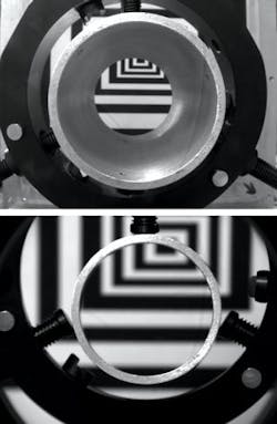
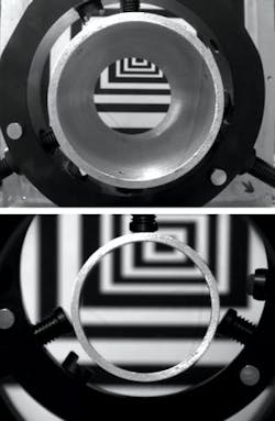
When standard optics are used to image 3-D objects, distant objects will appear smaller than those farther away. As a consequence, when an object such as a cylindrical cavity is imaged, the top and bottom circular edges appear to be concentric and the inner walls of the cylinder are imaged (common optics behave like human eyes when looking inside a cup or a glass). However, by using telecentric optics, the bottom edge and inner walls disappear and therefore the telecentric lens gives a 2-D view of a 3-D object, making the machine-vision system work more or less like CAD software (see Fig. 1).
Magnification changes
Telecentricity defines how the amount of magnification of an object within the field of view (FOV) changes with object distance. Thus, for the same FOV, objects being imaged with a long focal-length lens will exhibit less of a magnification change than those being imaged with a short focal-length lens. Because telecentric lenses act as if they have an infinite focal length, magnification is independent of object distance. Although objects moved closer or further from the lens may vary in focus, the image size of the object will be constant.
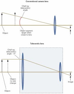
The degree of telecentricity of a specific lens is measured by the chief ray or telecentric angle (see Fig. 2). While standard commercial lenses may have telecentric angles of 10° or more, telecentric lenses have chief ray angles less than 0.1°. To achieve this level of telecentricity, the objective element must be larger than the FOV of the object to be imaged, making such lenses larger and thus more expensive.
In choosing a telecentric lens for a particular machine-vision application, system integrators must understand both the terminology used by individual manufacturers and the operational principles behind each lens design. Generally, telecentric lenses are supplied as object-space, image-space, or doubly or bi-telecentric designs (see Fig. 3). While many manufacturers offer these types of lenses, image-space telecentric lenses are more commonly used in image projection equipment and rarely in machine-vision applications.
In telecentric lenses, the chief ray through the center of the entrance or exit pupil is parallel to the optical axis, on one or both sides of the lens, depending on which type of lens is used. In machine-vision systems, the most often used of these lens types is the object-side telecentric. In these designs, the chief rays are parallel to the object being measured, and the lens system is used to focus the image onto a CCD or CMOS camera. Because these lenses are only telecentric on the object side, fewer lens elements are required than with bi-telecentric lenses, resulting in lower cost.
For either 2/3- or 1/2-in. format sensors, Edmund Optics offers two series of object-side telecentric lenses in its Techspec Gold Series. While the 2/3-in. series includes five lenses for use with either 2/3-in. or smaller sensors, the 1/2-in. series includes four lenses for use with 1/2-in. or smaller sensors. The 1/2-in. series maximizes field coverage by matching the largest FOV values for the 2/3-in. series, which allows for larger fields with smaller cameras. These lenses yield constant magnification over a defined depth of field and provide less than 0.2° telecentricity in the specified working distance range.
Object and image spaces
Many object-space telecentric lenses are offered with fixed focal lengths. However, in some machine-vision applications it may be necessary to optically increase the size of the captured image. To address these needs, some companies offer telecentric zoom lenses that allow the user to alter the focal length at the image place while retaining telecentricity on the object side of the lens. To achieve this, telecentric zoom-lens systems must automatically move the front-end optics and the stop between the front and rear lenses at different rates. Because these lens systems are more mechanically sophisticated than fixed-focal-length lenses, zoom telecentrics are offered by just a handful of companies.
The 12x telecentric zoom-lens system from Navitar, for example, provides telecentricity to within less than 0.3° while maintaining constant perspective and magnification. With a field coverage ranging from 50 to 4 mm at a 188-mm working distance, the 12x telecentric provides adjustable focal lengths over a 0.16x to 1.94x magnification range.
In some cases, especially for high-precision measurements, bi-telecentric lenses that provide telecentricity in both the object and image planes must be used to reduce the effects of optical aberrations and geometrical distortions. Because double telecentric lenses have infinite focal lengths, image size will not vary across the FOV due to the position of the sensor. Thus, bi-telecentric designs can have larger magnification depth of field and a larger range over which the object being imaged can move while still retaining the same magnification.
This is especially important because CCD and CMOS sensors continue to be developed with smaller and smaller pixels. To help focus light onto individual pixels, imager vendors are now incorporating microlens arrays onto their sensors. Placed over each individual pixel, these lenses are most effective when the incoming light rays diverge 5° or less from the normal. Because of this, bi-telecentric lenses, where telecentricity exists on both the object and image side of the lens, can focus incoming light in more effectively. Although these lenses are more expensive than single object-side telecentric lenses, they increase the accuracy of object measurement.
Another advantage of bi-telecentric lenses is even illumination. Due to the particular path of the rays in the image space where the ray cones are striking the detector surface with the same inclination, the pixels are illuminated with the same intensity over all the detector size. This feature is not very well known, but can be very useful for those applications where color homogeneity has to be controlled.
Lenses are offered by a number of companies including Navitar, Opto Engineering, Schneider Optics, and Sill Optics. Schneider Optical’s Xenoplan bilateral telecentric lenses, for example, are designed to work with 2/3-in. format CCD cameras and have adjustable iris and focus controls. These fixed focal-length lenses consist of five different models with fixed magnifications: 1:1, 1:2, 1:3, 1:4, and 1:5.
As Rolf Wartmann of Schneider Optics points out, when bi-telecentric lenses are not used as precision measurement lenses, asymmetric or drifting edge images arise when defocusing. This leads to inexact detection of edges, with the result that the degree of accuracy that is theoretically possible is clearly not attained. Bilaterally telecentric lenses do not exhibit these flaws, and thus make it possible to come close to the theoretically possible degree of accuracy (see www.schneiderkreuznach.com/knowhow/telezentrie_e.htm).
Fresnel lenses
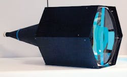
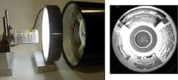
Object-space telecentric lens systems must have a front element that is at least as large as the FOV. Because of this, a conventional object space telecentric lens for viewing even a 16-in. field is both very expensive and very heavy (see Fig. 4). To overcome this, companies such as LightWorks have developed telecentric lenses that incorporate Fresnel lenses to reduce weight, cost, and length. Fresnel-based telecentric lenses are usually designed with the front element of a Fresnel form resembling a plano-convex or plano-concave lens that is cut into narrow rings and flattened out. Typically the Fresnel lens is made of thin, grooved molded plastic, and the rear element or elements are designed with conventional optics.
There is one big advantage of using Fresnel lenses as part of a telecentric system-they can be built to accommodate much larger FOVs than would otherwise be practical or even possible. The practical limit of a conventional telecentric lens is likely to be in the range of about 12 to 16 in. Light Works has designed and built Fresnel-based telecentric systems for FOVs as large as 42 in.
Despite their advantages, Fresnel lens-based systems are limited. Because Fresnel lenses have no color correction, it is usually best to use them with nearly monochromatic light such as LED sources. Otherwise, there is a likelihood of the appearance of color fringes around objects being imaged. Also, compared to conventional lenses, the image quality from a Fresnel lens is at best fair and may not be a good choice in highly accurate gauging applications or for detecting small defects. Light loss from a Fresnel lens is also relatively large due to light scattering at the grooves of the lens and the lack of antireflection coatings on the lens itself. Nevertheless, for lower-resolution applications a Fresnel-based telecentric lens can be a very practical and cost-effective solution.
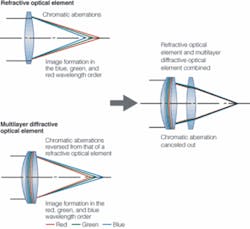
Interestingly, Canon claims to have overcome the problems associated with such lenses with its diffractive optics (DO) technology, which uses two single-layer diffractive optical elements whose diffraction gratings are bonded together face-to-face (see Fig. 5). Since longer wavelengths form an image closer to the lens due to the large diffractive angle, and shorter wavelengths form an image farther from the lens due to the smaller diffractive angle, putting the DO elements together with conventional glass optics cancels out chromatic aberrations (see Canon Web site). Unfortunately, the use of this technology has yet to find its way into telecentric lens-based designs.
null
Pericentric optics provide 360° views
Many machine-vision systems are used to inspect more than one face of a piece, and in many cases 100% inspection of a cylindrical or spherical surface is needed. In the past these inspections were made using an array of cameras placed around the part, with each camera capturing an image of a specific side or portion of the piece.
Unfortunately, this approach increases system costs because of the number of cameras required. In addition, the object being imaged must be precisely positioned, because each camera has to image the piece at a specific angle. To overcome these problems optical approaches have been developed such that only one camera is needed to achieve an image of all the features of a surface.
These lenses are called pericentric because of the path of the rays inside the objective-the aperture pupil is seen from object space as moving around the peripheral zone of the front optical group. They require just one camera to capture the image of both the front surface of an object and its surrounding sides. When the lens images a cylindrical object both the front surface and the cylinder surface are imaged at the same time.
The advantage of this approach, often used to inspect parts such as glass bottles, aluminium cans, and other consumer product packaging, is that all the object’s features can be imaged in the same frame and can be processed by a single algorithm to obtain a flat representation of the cylindrical surface.
Claudio Sedazzari
Opto Engineering
Mantova, Italy
www.opto-engineering.com
