Optics Matter
Machine-vision lenses must be tailored to perform as needed for accurate, high-speed imaging
Optics are a critical component for an industrial imaging system. They control the quality of the image sent to an analyzer and can be the difference between a high-performance machine-vision system and a poor one. Yet, integrators either view the optics as an afterthought—thinking any lens will do—or are intimidated by the jargon involved in rating lenses. In addition, many integrators consider only cost, settling for an inexpensive lens that seems to have the right ratings but that ultimately results in poor performance.
There is a great deal of difference between the lens in a commercial camera, a professional photographic lens, and a lens designed specifically for machine vision. Rating lenses can be a delicate balancing act, involving the consideration of optical terms such as light loss, light fall-off, poor MTFs, focus and vibration, telecentric error, aberrations, and shallow depth of field. But selecting the optics for a machine-vision system need not be a daunting task. In general, you’ll want to make sure that you have a lens that can form the basis of a reliable system, is reasonable in cost, and is practical to integrate. Machine-vision lenses have all these features.
Use only what you need
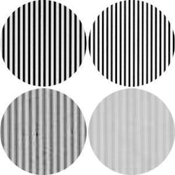
Some integrators take the approach of buying the highest-quality lens just to be safe. Sometimes highest quality can be an ambiguous description. A lens may perform well and provide good contrast at high resolutions but produce relatively poor-quality images and poor contrast at lower resolutions. If your application inspects features at relatively low resolutions, paying a lot more for such a lens is unnecessary (see Fig. 1).
FIGURE 1. Images show the difference in contrast using the same lenses to view objects of different resolution. Two backlit targets, one with high-frequency (high-resolution) lines and one with low-frequency (low-resolution) lines were imaged using a 2/3-in. monochrome camera with 50-mm lenses from different suppliers. Lens 2 costs five times as much as Lens 1 and provides better contrast for low-resolution objects. Lens 1, on the other hand, provides better contrast for high-resolution objects. Thus, object resolution determines the best lens for an application. [Note: The images displayed show a magnified portion of the full image]
In some applications a high-quality lens may appear to be a large, professional photographic lens. This type of lens tends to have a low F-number, which allows great light-gathering capabilities for a very good perceived image quality. The obvious downfalls of this type of lens are size and cost. A lens like this can be heavy, and some industrial environments simply will not allow a lens of this size. Another drawback is the lack of design features, such as locking knobs on the focus and aperture adjustments. Such features are required in some high-vibration or unpredictable environments to ensure consistent images.
Another reason that large professional lenses are not used for many industrial applications, despite their great light-gathering capabilities and visual image quality, is that they are not designed for machine-vision algorithms. Professional and commercial cameras and lenses may not have what is needed for a machine-vision application in terms of image quality, since the metrics used to determine a visually pleasing image are different than the metrics used to determine an acceptable image for accurate measurement systems.
Have what you need
Since the metrics for visually pleasing images and machine-vision images are different, it is important that the lens you choose can deliver the image quality that your system needs. At first glance, the price of consumer lenses may be appealing. Why not just use a commercial digital camera with the optics already included? You may think that the images from your weekend adventures look better than any industrial images you’ve seen. The reason for this may be that commercial lenses are designed for acceptable image quality according to human aesthetics.
For example, we don’t need to measure the width of a pine tree or detect how many leaves are at the edge of the image. There can be a decrease in image quality at the edge of a portrait, and that actually helps us focus our attention on the subject, which is usually near the center of the image. There can also be a degree of distortion in a portrait, and we won’t detect it with our human visual system.
However, if we were trying to count the number of leaves at the edge of the image with a commercial camera, our algorithms would either do a horrible job or become more complicated. As the aberrations increased and the relative brightness and contrast of the image decreased at the edge of the image, the thresholds and edge detection settings would no longer be useful.
Software can always be used to calibrate and compensate for uneven illumination and distortion. Remember that engineering and development time is also an expense, and avoiding such costs and extra work can also avoid headaches. One thing that software cannot do is recreate lost information (although it may be able to interpolate it).
Distortion is another optical aberration that can be calibrated and corrected with software. Distortion within an image is not linear, though, nor is it always monotonic. These types of optical characteristics can make some measurement algorithms more useful or rugged than others. Since many industrial applications require accurate measurements to be taken across the entire camera sensor, machine-vision lenses are designed with such requirements and software capabilities in mind. There are a variety of additional optical aberrations and phenomena that are not typically corrected with software, so it is up to optical designers to minimize or balance them during the design phase.
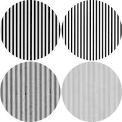
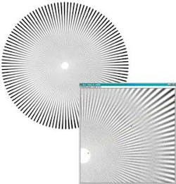
It does not make sense to overpay for unused image quality, but if a complete vision system costs about $60,000 and it does not work because a $200 lens was used rather than a $500 lens, it becomes apparent that the lens of an imaging system is more than just an accessory. Many large-format applications demand a lens that can provide high resolution across a large camera sensor with small pixels. Paying for a higher-resolution camera will not be a benefit unless the lens can keep up. If the resolution of the lens and camera are not matched, you can get interesting effects such as contrast reversal at high resolutions (see Fig. 2).
FIGURE 2. If a vision system was intended to measure the length of the white lines this effect would cause erroneous results. Image on the right shows the contrast reversal due to reduced image quality.
Lenses for industrial applications must be chosen based on the goals of the installation and the capabilities of other components in the system. Although an image may look good to a human observer, it may not have the clarity and contrast needed to provide accurate information for a machine-vision system. Lenses designed specifically for machine-vision applications have the performance needed for accurate, high-speed imaging. As a result, designers don’t have to settle for images that just look good but get images that supply the needed information.
Using a lens
All lenses collect light and form an image based on the same optical principles. There are some guidelines that can help integrators set up their imaging system regardless of the type of lens specified for the system.
Manipulating the amount of light: Getting the optimum amount of light will depend on the lighting source used, the camera exposure settings, and the light gathering ability of the lens. The f/# setting controls the light gathering ability of a lens. A lower f/# will allow more light into the system, and a brighter image can be obtained. A higher f/# will allow less light to be collected, and an overexposed image can be avoided. The working f/# of a lens is an integral part of controlling the shutter speed (integration time) and frame rate of an imaging system. For example, if an object is moving fast, a fast frame rate and short integration time may be required. To make up for the loss in light (and dark images), the f/# of the lens can be increased.
Although f/# is a useful number to describe the amount of light being collected by a system, it is not a definitive way to compare the light-gathering capabilities of lenses, especially from different suppliers. One reason is that the f/# depends on the working distance. The f/# can be defined at infinite conjugate (when the lens is focused at infinity) or a particular finite conjugate. It does not make sense to compare the f/#s of two lenses if they are specified at different conjugates, especially if you will be using the lens at still another conjugate. The other reasons to consider are the various lens-design techniques used to increase throughput, such as antireflection coatings. Lenses may also have a considerable decrease in illumination near the edge of the image, which you would not know simply from the f/#.
Manipulating depth of field (DOF): Depth of field defines how much of an object is in focus. The f/# setting of a lens affects the DOF. In general, increasing the f/# will increase the DOF. At some point the image quality and, therefore, the apparent DOF will decrease with an increase in f/#, but understanding that f/# can control the amount of DOF is a useful tool.
Focusing a lens at its hyperfocal distance is a useful way to obtain the maximum amount of DOF. The hyperfocal distance can easily be determined for any fixed-focal-length lens that focuses to infinity. When the lens is focused at infinity, the hyperfocal distance is the closest distance to the lens that is still in focus. If you mark this distance and then refocus the lens at this distance you will obtain the greatest amount of DOF possible. Everything from one-half the hyperfocal distance to infinity will appear in focus. Hyperfocal distance is dependant on f/# since DOF is dependant on f/#(see Fig. 3).
FIGURE 3. When a lens is focused at infinity, the hyperfocal distance is the closest distance to the lens that is still in focus. Refocus the lens at this distance to obtain the greatest amount of DOF possible. Everything from one-half the hyperfocal distance to infinity will appear in focus.
DOF is another characteristic that is difficult to compare from one system to another. That is because it can be difficult to define what is ‘in focus’ and what is ‘out of focus.’ Only one distance from the lens is in ‘best focus.’ A good way to visualize focus is to image a very small point of light. When that point of light is located in the object plane of best focus, the image is a very small point. As the point of light is moved out of the plane of best focus, the image becomes a larger, blurred circle. As long as the diameter of this blurred circle is less than the size of one pixel, it will still appear to be in focus in the image (see Fig. 4).
Since most objects are not perfect little points of light, image blur may not be noticeable even when it is greater than 1 pixel. If the blur of an object at a certain working distance is small enough so that a machine-vision algorithm can still properly detect the objects, then it is considered ‘within the DOF’.
Understanding optics can often help in creating more flexible imaging solutions for environments with space constraints. Adding folding mirrors, changing working distances or zoom settings, or adding spacers or focal-length extenders can all be done to achieve the desired FOV. Locking screws can be replaced with setscrews or glued to ensure they are not changed. Many such tricks can be utilized to help with integration and ensure consistent images.
Jessica Gehlhar is an applications engineer at Edmund Optics, Barrington, NJ, USA; www.edmundoptics.com.


