Testing, testing
Machine-vision lens manufacturers can choose from a variety of test systems to evaluate their products
System integrators can choose from a range of lens suppliers and products when configuring their image-processing systems. Choosing a lens, however, is often made more complex by the lack of technical information supplied by vendors. Although figures such as magnification, working distance, and numerical aperture are often quoted in data sheets, other parameters such as modulation transfer function (MTF), color aberration, and quantitative analysis of image quality are generally omitted from these data sheets. In high-precision image-processing systems, however, designers need to know these parameters to properly determine whether a specific lens is optimal for their designs.
Luckily, a number of optical test systems are now available that allow developers to evaluate published and unpublished lens specifications. At Photonics West 2008 (San Jose, CA, USA), Optikos, Trioptics, and Wells Research and Development demonstrated some of these systems, which provide the only way to accurately determine the true specifications of off-the-shelf and custom lenses.
According to Harvey Miller, president of Mildex, the Trioptics US representative, the company has already deployed these systems at companies such as Janos Technology, Lockheed Martin, and Zygo. Today, a large budget is not required to perform testing, with Optikos, for one, offering third parties its services at $250/hour. Mildex can supply optical testing systems at every budget level—from prototype testing to full production testing models.
Despite the variety of test systems now available to evaluate optics, the system operating principles are similar. The lens under test is mounted between a collimated light source and a video microscope. This light source projects an image from a test reticule onto the lens, and the image is captured by the video microscope’s camera. Because the microscope can be mounted on a three-axis adjustable mount, the lens can be rotated for off-axis testing.
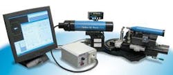
In the design of their systems, vendors have chosen different methods to illuminate and capture projected images. Optikos, for example, uses a FL1500 halogen light source from Schott North America in the design of its QC Bench automated optical test instrument (see Fig. 1). For its OS210B optical test system, Wells Research has opted to use an LED light source, that, according to company president Ben Wells, is brighter, more stable, and more uniform than the halogen light source used in the company’s previous generation OS210A (see Fig. 2).
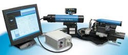
Figure 2. Wells Research and Development OS210B is a table-top system for testing lenses with focal lengths from 0.5 to 500 mm. Although the base system is operated manually, motorized stages are available for one, two, or three axis.
In the design of the OS210B, there are four LEDs consisting of three narrow-band colors and a broadband white. “Illumination intensity is adjustable over a 300:1 range with no shift in color temperature,” says Wells. Designers also have a number of choices of cameras and frame grabbers used to capture images. In the Trioptics Optispheric system, for example, the company has chosen to use a digital 1/3-in. CCD Camera Link camera that transfers images to a PC using a frame grabber from Leutron Vision (see Fig. 3).
For its QC Bench system, Optikos has used an ST400 RS-170 analog camera from Sentech America. Analog signals for this camera are transferred to the system’s host PC using a frame grabber from Mutech. “Although not featured at the show,” says Anthony Abdulla, marketing and communication specialist at Optikos, “the company offers a replacement for this analog setup featuring a FireWire camera directly attached to the PC.”
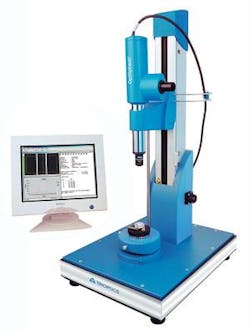
Figure 3. Trioptics Optispheric is an automated optical test instrument used to characterize optical components and lens systems. Using the system, optical parameters such as effective focal length, MTF, and back focal length of lenses with diameters from 2 to 200 mm and EFL from 1 to ~2000 mm can be automatically measured.
To properly determine the image quality obtained from a lens, developers must measure the spatial-frequency response of the system. This measurement, known as the MTF, establishes how well the contrast of an image is preserved in percentage terms after the image passes through the lens. Of course, the results of this measurement can also be affected by the camera used to capture the image.
“Unless the image reflects the flaws of the lens under test and only those flaws,” says Wells, “the calculated MTF will be of dubious value.” However, since the MTF of the camera can be calculated from the pixel size and pixel pitch of the sensor and the total system MTF is a product of both the MTF of the lens and the MTF of the camera system, the MTF of the lens can easily be calculated. Of course, such sophisticated measurement systems can be used to calculate more than the MTF of a lens.
Indeed, Optikos, Trioptics, and Wells Research and Development all offer systems that can be used to calculate focal length, field curvature, distortion, and chromatic aberration and display the results on a PC-based graphical user interface. With the availability of these test systems, vendors of relatively expensive lenses should now be able to provide technical specifications of their products to their customers.
null


