Gearing up for Power over Ethernet
After the introduction of the Camera Link standard, camera vendors looked for a means to lower the costs of cabling needed to both power and transfer data from these cameras. What emerged was the Power over Camera Link (or PoCL) standard that reassigned pins, originally assigned as ground, as power lines. This allowed vendors to develop cameras that required only one MDR-16 connector with the added benefit of delivering a maximum 4 W of power to the camera.
Now it appears the same scenario is about to emerge for the Gigabit Ethernet standard. Rather than wait for the Automated Imaging Association (Ann Arbor, MI, USA; www.machinevisiononline.org) to develop or endorse any specific standard, camera vendors have started to adopt the IEEE 802.3af standard in their latest powered GigE cameras. But just as PoCL cameras require power to be provided from frame grabbers, the latest powered GigE cameras will require specialized networking hardware in the form of switches.
Ratified in 2003, the IEEE 802.3af specification allows power to be supplied in parallel to the data over existing Ethernet cables. PoE-based cameras connected to the Ethernet can thus use Ethernet cable to obtain up to 13 W from the network. The IEEE 802.3af specification currently defines two different implementations to deliver this power. The first, known as Mode A, defines the power feed on the 1-2 and 3-6 data pairs. The second method, Mode B, uses the unused data pairs 4-5 and 7-8 to supply this power.
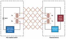
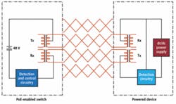
“Ethernet cabling contains four pairs (eight wires),” says Dietmar Scharf of Baumer Optronic (Radeberg, Germany; www.baumergroup.com), “and because 100base-TX implementations use two pairs of them, it is possible to use the other (spare) wires for supplying power over the Ethernet cable. This is Mode B. “However, Gigabit transmission (1000base-T) uses all four pairs and so there are no spare wires.” Thus, power must be transmitted over the data lines (Mode A). In this configuration, two pairs are only for data transmission, and two pairs are shared for data and power in a so called phantom circuit” (see Fig. 1).
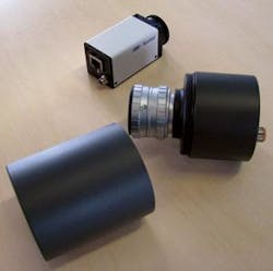
This is the method used by Baumer in its latest TXG series of 13 GigE cameras shown at VISION 2007 in Stuttgart, Germany (see Fig. 2). Because two GigE pairs are shared for data and power, designing PoE-based cameras requires minimizing any signal degradation of the data signal so that low-noise images can be accurately reproduced. Interestingly, even in the company’s fastest camera, the TXG03c, 90-frame/s, 656 × 494-pixel CCD color camera, the power requirement is approximately 4 W, well below the maximum 13 W specified by the PoE standard. The challenge of incorporating power into GigE-based cameras has so far limited the number of companies that offer such products, although many low-cost PoE cameras are currently available that target the less-stringent security market.
To power these cameras, system developers will need to choose specialized networking hardware in the form of end-spans (or Ethernet switches) or mid-spans that include PoE circuitry. This so-called power sourcing equipment (PSE) feeds in Mode A or Mode B and is not influenced by the powered device. While end-spans or PoE Ethernet switches can directly power GigE cameras in either Mode A or Mode B, mid-spans are used in legacy 100base-TX Ethernet installations where existing unpowered switches are already in use.
Placed between the existing switch and the power-enabled devices, these mid-spans add power to existing Ethernet connections. Unfortunately, because the IEEE 802.3af specification dictates that these devices only use Mode A, power is thus delivered over the unused Ethernet pair. Because GigE cameras use this pair to transmit data, such mid-spans cannot be used to transmit power over a Gigabit Ethernet connection.
A number of large networking companies including Cisco (San Jose, CA, USA; www.cisco.com), 3Com (Marlborough, MA, USA; www.3com.com), and Hewlett-Packard (Palo Alto, CA, USA; www.hp.com) already offer PoE GigE switches. Using these switches in conjunction with PoE-based cameras will allow developers to reap the benefits of 100-m cable lengths and reduce system costs by eliminating power cables.


