Optics & Lenses: Smart optics and lenses image multiple views
Many machine-vision systems are required to analyze multiple features of an object simultaneously. For example, in bottle inspection it may be necessary to view the circumference of a container and check for any defects in the neck. Inspections often are performed using multiple cameras placed at strategic locations within a machine-vision work cell. Although these systems are effective, multiple cameras increase the cost of vision systems and, in some cases, can limit system performance.
Of course, other systems such as linescan cameras can also be used to inspect the surface of an object. However, linescan-based systems also suffer from technical and cost concerns; parts to be inspected must be brightly illuminated and rotated within the camera’s field of view (FOV).
For these reasons, system developers often look to optics vendors to provide single-camera solutions that alleviate the need for part rotation. To accomplish this, many different types of optics, lenses, and optical-lens combinations can be used, including pericentric lenses, specialized optics to inspect holes, multimirror systems, and optical probes.
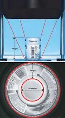
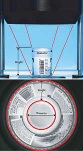
When the outer surfaces of parts moving on a conveyor must be inspected, multiple-camera systems often cannot be used because neighboring parts may obstruct the side views of the object under inspection. However, by using pericentric lenses with a single camera, a 360° image of the top and sides of the object can be captured. In this system, an image of the lateral walls of the object is displayed around the image of the top surface of the part (see Fig. 1). Pericentric lenses simplify system integration because the parts to be inspected can pass freely in the space below the lens. Captured images are then unwrapped using software to obtain a linear view of the sides of the object and allow image analysis to be performed.
Inspecting the other surfaces of objects also can be accomplished by using multiple-mirror systems. In this approach, an object is viewed through a mirror assembly using a telecentric lens, which allows four or more different side views of the object to be obtained (see Fig. 2). Because a telecentric lens is used, all the images are magnified equally, allowing them to be correctly matched and measured using software.
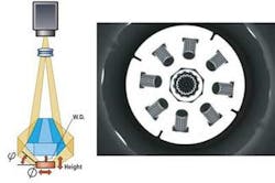
One variation of this technique that provides multiple side views of the same object can be achieved using polyview optics. These multimirror optical systems provide four, six, eight, or more side views of the same object. This makes the system suitable for inspecting the inner and outer surfaces of objects such as washers or grommets. Since the inner and outer side surfaces are displayed in the same image, all the relevant information needed to inspect the products is simultaneously displayed (see Fig. 3).
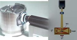
In some cases, other optical solutions can be more efficient and compact. When cavities need to be inspected, specialized optics can be used to generate images similar to those provided by pericentric lenses. Like pericentric lenses, the optics are designed to image curved surfaces. The wide perspective angle obtained provides a detailed view of these surfaces without the need to place an optical probe inside the part (see Fig. 4).
Although these optics are useful, they cannot be used to image the interior of threaded objects. In this case, it is necessary to insert a fiberscope or borescope inside the part, which uses bundles of coherent optical fibers to transfer images from the cavity to a camera. Unfortunately, the maximum number of fibers a bundle can contain limits the achievable resolution, and when high-resolution images are required, a direct optical coupling with the camera must be used. This can be achieved by using optical probes that consist of a macro lens that images the cavity walls through a spherical or aspherical mirror (see Fig. 5). Optical probes alleviate the need to scan the entire thickness of the cavity if the inspection can be limited to a specific cavity height.
However, when defects inside a cavity become very small, a much higher optical magnification is needed and a smaller FOV is required. Since only parts of the interior surface can be inspected in a single image, the probe must scan the height of the cavity and rotate to provide a full 360° view. Besides requiring an accurate positioning system for probe movement, this also requires specific software for image matching, since the image of the cavity will consist of numerous images obtained by scanning the interior surface and depth of the cavity.
—Claudio Sedazzari, Opto Engineering
Mantova, Italy
www.opto-engineering.com


