Eye Defense
Andrew Wilson, Editor
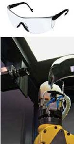
Protective eyewear destined for military use must withstand the effects of different types of munitions and be free of defects such as scratches, pits, or bubbles. The eyeglasses are molded from impact-resistant polycarbonate that is covered with a scratch-resistant coating. In addition to inspecting these eyeglasses for defects within the polycarbonate itself, any drips or runs caused by the application of the scratch-resistant coating must also be detected during the manufacturing process.
To ensure its product has no such defects, a US-based eyewear manufacturer called upon AV&R Vision & Robotics to develop an automated inspection system capable of analyzing surface defects.
“Usually,” says Michael Muldoon, business solutions engineer with AV&R, “surface imperfections on the eyeglasses are inspected manually and compared to a scratch and dig paddle.” The paddle, available from Edmund Optics and other suppliers, is a means by which any scratch or dig in the surface can be compared.
Using the paddle, any defect is defined by a scratch number followed by the dig number. This standard was developed during World War II from Frankford Arsenal in Philadelphia, PA, and is based on the appearance of a scratch. Because different scratch structures could have the same appearance, it is difficult to determine the physical size of these standards. But they are still in use for optical quality requirements. In highly demanding optical quality, as in the defense industry, the biggest crack acceptable in the viewing area is a scratch-dig of 20-10, which roughly corresponds to 2-μm width scratch and 1-μm diameter dig.
Rack them up
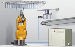
After each individual lens blank is molded and coated, it is placed in a rack that can contain between 6 and 24 pieces, depending on the type of lens being manufactured. This rack is then manually placed inside the inspection work cell (see Fig. 1).
FIGURE 1. To perform automatic surface inspection of military eyewear, AV&R has developed a robotic-based work cell that uses robots and vision to inspect eyeglass blanks at a rate of approximately 15 parts per minute.
“As each rack is barcoded,” says Muldoon, “a SICK barcode reader within the work cell is used to identify the type of lenses on the rack, how many there are, and how they are positioned.” Before any optical inspection can be made, each individual lens pair must be moved to an inspection station located in the work cell.
After the system’s host PC reads the barcode of each batch, the information is interpreted by a robot controller from Fanuc Robotics that instructs an LR Mate 200 IC robot to pull each lens blank from the rack and attach it to a pneumatically controlled gripper placed within the field of view of the optical inspection system (see Fig. 2).
FIGURE 2. In operation, a robot is used to pick eyeglass blanks from a rack and mount them onto an optical inspection system where they are rotated in front of a linescan camera.
“After the first lens blank is placed on the gripper,” says Muldoon, “a motor equipped with a rotary encoder moves the eyewear 180° across the field of view of a 4k × 1 linescan camera from DALSA. This image data is then transferred across a Camera Link camera interface and stored in the system’s PC. In this way, the system is capable of building a precise 2-D image of the surface of the eyewear.”
Because the system uses a linescan camera with which to capture image data and because of the nature of the defects to detect, it was necessary to use a specially designed illuminator to backlight each part as it moved across the field of view of the camera. To accomplish this, AV&R chose custom-designed lighting from Boreal Vision that provided the brightness and even illumination required.
Scratches, pits, and marks
Several types of defects can be present in both the eyewear itself and the surrounding mold. These include handling defects such as scratches, pits, or marks and process defects such as bubbles, drips, runs, and contamination. Because defect tolerance varies in different zones within the eyewear, the imaging system must first be taught to recognize those zones.
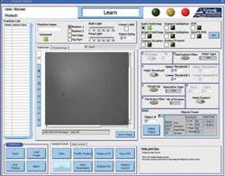
To accomplish this, AV&R used LabVIEW from National Instruments to first define the region within the captured image. After defining the region of interest to be analyzed, a specification was developed that stipulates the density of imperfections that can be allowed based upon the area in which they are found. If, for example, a small scratch not greater than #40 is found in an area close to the rim of the eyewear, then the part may be passed. If such a defect is found toward the center of the eyewear, then the part may be classified as faulty.
“The operator can control the defect detection and segregation algorithms to define the types of defects and set specific pass/fail thresholds based on their size, shape, and location,” says Muldoon (see Fig. 3). After an image of the eyewear is captured, these defects are located by first performing a threshold operation and then performing blob analysis on the thresholded image. By comparing each scratch to those specified on the scratch and dig paddle, each scratch can be classified. Depending on the width of each scratch, the part is classified good or bad. Similarly, any bubble or pit greater than 0.15 mm within a critical area of the eyeglasses is also classified as a defect (see Fig. 4).
null
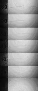
FIGURE 4. Defects such as scratches are classified according to a standard scratch and dig test while defects such as pits must be rejected if they are larger than 20-μm diameter.
After this inspection is complete, pass/fail data generated by machine-vision software running on the PC is used to actuate the gripper releasing good parts onto a conveyor. Should the part be bad, the rotary arm is moved 45° and the part released into a reject bin. At the same time, the Fanuc robot loads the next lens pair onto a second robot gripper located opposite the first. “In this way,” says Muldoon, “the system can inspect a single lens blank once every 3.5 s.”
The human touch
“In the development of the system,” says Muldoon, “it is vital that the machine be capable of performing equally well as a fully trained operator.” To ensure this, the test protocol involves a random sampling of 100 eyeglass molds to be cycled though the system three times. After the image data are analyzed, they are compared with results obtained by a human operator and a Kappa test is used to determine the degree of agreement between the two results.
“By performing this test, the system can be adjusted so that the agreement between the human operator and the automated inspection is acceptable,” says Muldoon. “In this way, our customer is assured that the system is capable of performing at least as well and often better than a human operator.”
Company Info
AV&R Vision & Robotics
Montreal, QC, Canada
www.avr-vr.com
Boreal Vision, Montreal, QC, Canada
www.borealvision.ca
DALSA, Waterloo, ON, Canada
www.dalsa.com
Edmund Optics, Barrington, NJ, USA
www.edmundoptics.com
Fanuc Robotics
Rochester Hills, MI, USA
www.fanucrobotics.com
National Instruments
Austin, TX, USA
www.ni.com
SICK, Minneapolis, MN, USA
www.sickusa.com
CAD software eliminates manual testing of samples
A machine-vision system usually requires a human operator to train the regions of interest to be inspected and the types of defects to be detected. Once analyzed, the data are compared with data obtained by a human operator. However, difficulties arise when guaranty must be given about the inspection coverage, especially when complex shapes occur. “To eliminate this process,” says Michael Muldoon, business solutions engineer with AV&R, “AV&R created a surface-inspection development environment (SIDE) that allows CAD models of each part to be used in a virtual simulation environment.”
SIDE was developed using NI LabVIEW and is currently an internal tool that enables AV&R’s engineers to be more efficient in deploying and designing systems as well as in working remotely with customers to train new part numbers and validate inspection routines.
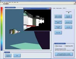
Using AV&R’s surface-inspection design environment (SIDE), engineers can simulate in 3-D the vision system, lighting, how the robot manipulates the part, and the part-light-camera interaction during inspection.
During the robotic surface inspection of an aircraft engine turbine airfoil, for example, more than 100 images may need to be analyzed, all taken from different positions.
In the past, the training of the inspection routine was all done manually using the teach pendant of the robot and separate vision software. The coverage capability was estimated based on received samples and tests. This type of training can be tedious, time consuming, and risky from a performance standpoint.
Using SIDE, the system developer can simulate in 3-D the vision system, lighting, how the robot manipulates the part, and the part-light-camera interaction during inspection. “In this way,” says Muldoon, “part defects can be simulated and the results of any light reflected from them can be used to control the position of a simulated robotic-based vision system.” Then, before any system or new part number is deployed into production, the system developer will have developed the entire inspection routine offline, including the robot path and required vision tools.
The software seamlessly performs a robot simulation to test each position, ensuring the robot can reach every point safely. This routine is then downloaded to the system for validation. SIDE also features a reverse engineering routine that takes the configuration files from a system in the field and performs a validation on the entire sequence.
Using modeling techniques, SIDE ensures all areas of the part have been inspected and for each area the correct angles of inspection have been established. This ensures all the defect types and orientations have been accounted for, which is critical for components destined for the aerospace and medical industries.
