Circuit Makers
Winn Hardin, Contributing Editor
A thermistor is a small thermal switch used in most electronic systems to protect them from excessive heat. It is essentially a small bimetal disk soldered between two electronic leads. When the disk reaches a certain temperature, the differences in thermal expansion between the two metals cause the disk to move quickly, or snap. The movement breaks the circuit, relieving the system from the electric load, which allows the temperature to drop to safe levels.
The GE Sensing plant in St. Mary’s, OH, manufactures dozens of varieties of thermistors. While many manufacturers still use manual sampling methods rather than 100% in-line inspection to qualify the thermistor and make sure the disk is adequately soldered between the leads and that the neither leads nor disks are damaged during manufacture, GE Sensing adopted a machine-vision quality assurance system several years ago. With recent upgrades to its thermistor manufacturing line, GE Sensing decided to upgrade the aging analog machine-vision system to a digital system that could perform additional inspection checks with less downtime and maintenance.
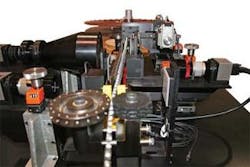
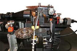
Aptúra Machine Vision Solutions designed an inspection system for thermistor tape reels using three PPT Vision Impact smart cameras networked to a PC running a custom user interface (UI) with data archiving. The system inspects more than a dozen physical criteria at a rate of three thermistors per second on tape reels (see Fig. 1).
FIGURE 1. The thermistor inspection system developed by Aptúra Machine Vision Solutions inspects solder coverage of the bimetal disk as well as various component dimensions.
Two-faced viewing
GE Sensing wanted the thermistors inspected from both sides to verify product viability. The in-line inspection system is located just after the disk soldering process. The thermistor tape is advanced by automation at both ends of the overall process. Within the vision station, interchangeable pin guides and rails are used to maintain product stability for the inspections.
“We look at the product after the disk is assembled to the two leads with wave soldering,” explains David Dechow, president of Aptúra. “We look at both sides of the disk head and do some measurements, primarily for solder detection. We’re not looking at solder quality, which is a very difficult machine-vision task, but solder coverage. We’re also looking for chips out of the thermistor disk, the placement of the disk between the leads, and that the leads are centered and not angled or bent.”
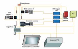
The tape passes in front of three PPT Vision Impact smart cameras, each with its own processor unit. The Ethernet networked Impact vision systems work independently while the vision station HMI industrial PC collects the data from all three cameras, stores images of defective parts, and serves as an operator interface for easy configuration of inspection parameters.
All three camera systems interface via discrete I/O to a station PLC from Unitronics, which tracks parts and sends rejection signals to a specially designed cutting unit that flags defective thermistors by cutting one of the terminal legs just before the pick-up reel (see Fig. 2). Because the thermistors are spaced evenly on the pinhole tape, a precision through-beam sensor from Banner Engineering triggers each camera as a light beam passes through the pinhole and activates a photoeye on the far side of the thermistor tape. “There’s one pinhole per part, so we get one trigger per part,” adds Dechow.
The three cameras are positioned on linear slides for fine-tuning camera position along the length of the tape. This allows system engineers and maintenance to adjust camera placement as necessary should GE Sensing switch to a tape reel with different offsets between each thermistor, or to replace a camera or lens (see Fig. 3).
FIGURE 3. Each camera is placed so that a single trigger based on a SICK pinhole sensor can trigger all three cameras to capture an image of a different thermistor on the tape.
Red and blue success
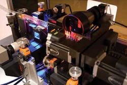
As the tape passes the first camera system, the Banner sensor passes a signal that triggers the cameras. The tape passes between two lights and in front of one Impact camera with a high-resolution, short-working-distance lens from Edmund Optics. In front of the tape resides an on-axis blue LED array from CCS America that forms a window for the CCD camera. A red LED backlight sits behind the tape.
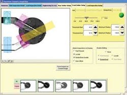
“Solder will reflect any color of light, but it turns out that in the absence of solder, blue light reflects better from the disk surface than from the solder,” explains Dechow. “To see if the solder is present or not, we do edge detection on the image, look at the solder area, and see if there is any bare thermistor material.”
He adds, “At the same time, we strobe the red LED backlight. The red light is relatively dim compared to the frontlight. The purpose of the red light is to provide a silhouette profile so we can do a dimensional check for chips on the edge of the thermistor and perform other geometric measurements.”
By balancing the relative illumination between the blue frontlight and red backlight, Dechow says they can do both front-side solder inspection and chip geometric and quality inspections using the same image.
The tape continues to a second Impact camera that performs the same operations from the other side of the tape.
Telecentricities
After both sides of the disk and solder have been inspected, the thermistor proceeds to the final inspection station. A third Impact camera with a CVI Melles Griot telecentric lens captures a picture of the entire thermistor, from the tip of the leads to the bimetal disk.
“We needed a telecentric lens because we’re imaging thermistors that can be up to 48 mm long with resolution of ±0.04 mm and without distortion,” explains Dechow.
Another red LED backlight outlines the thermistor for the third camera. The Impact processing unit uses edge detection and linear measurements to gauge the width of each lead or terminal leg, the distance between the legs across their entire length, the offset or length of the leg to make sure they are even, and the straightness of the legs.
FIGURE 4. By balancing relative illumination between a blue frontlight and red backlight, the system can perform frontside solder inspection and chip geometric and quality inspections using the same image.
Dechow says that the client had chosen the Impact system for a variety of reasons. “Machine-vision hardware is essentially an image delivery device,” he notes, “and there are a lot of ways to deliver an image. What’s important is the software, which is very strong, with a good logic flow, task-driven language, and access to lower-level functions, including the data flows within the Impact processor itself.
“Many vision suppliers have good tools,” Dechow says, “but they won’t always expose all the parameters to the integrator. Impact has software constructs like data manipulation, looping, branching, and interrupt-driven tasks. It also comes with an object-based HMI that lets you customize it for the customer, rather than just add some forms and buttons based to a manufacturer’s canned HMI. The system can be seen as a little more complex, but you get extra programming capabilities.”
Dechow adds that, given the centralized inspection process and proximity of the three cameras, a PC-host system with three cameras would have been a viable alternative to using three smart cameras, but customers are comfortable with smart cameras.
After all inspection tasks are completed, images of defective parts are stored locally on the operator’s Stealth Computer industrial PC. Defect data is captured by the thermistor inspection system, but so far, GE Sensing has not requested a statistical process control (SPC) database for batch review.
At the end of the inspection station, the PLC that tracks rejected parts signals the reject mechanism to perform a cut on one leg of any part flagged as defective. The reject trigger alternates between two cutting mechanisms to ensure the cutting of each leg in the event that multiple parts fail in sequence at maximum throughput.
Each cutting mechanism uses a servo motor to drive an eccentric gear that translates the rotary motion into high-speed linear motion during a single rotation of the motor. The cutter itself is a hardened steel shear.
Company Info
Aptúra Machine Vision Solutions
Lansing, MI, USA
www.aptura.com
Banner Engineering
Minneapolis, MN, USA
www.bannerengineering.com
CCS America, Burlington, MA, USA www.ccsamerica.com
CVI Melles Griot
Rochester, NY, USA
www.cvimellesgriot.com
Edmund Optics, Barrington, NJ, USA
www.edmundoptics.com
GE Sensing, Billerica, MA, USA www.gesensing.com
PPT Vision, Bloomington, MN USA www.pptvision.com
Stealth Computer
Woodbridge, ON, Canada
www.stealthcomputer.com
Unitronics
Ben Gurion Airport, Israel
www.unitronics.com
