The Infrared Choice
Andrew Wilson, Editor
Despite being relatively expensive, infrared (IR) cameras have found a number of niche applications where traditional visible spectrum CCD and CMOS cameras will not suffice. Examples include building maintenance, flame analysis, gas monitoring, semiconductor inspection, and industrial machine vision. When selecting a camera to meet the demands of these applications, system integrators must carefully consider the characteristics of objects to be examined and the type of detector and its photosensitivity needed to fulfill the requirements of the task.
Infrared cameras can be classified into thermal and quantum types. Thermal detectors—the most common of which are microbolometers—often use amorphous silicon and vanadium oxide detectors that change their resistance when subjected to changes in temperature. These detectors measure the heat emitted by an object, and their photosensitivity is independent of wavelength.
This quality makes the detectors useful in cameras that can image the 0.75-to-14-μm spectrum, but they are less sensitive than quantum-based detectors and, due to their relatively slow response time, cannot be used in high-speed IR applications.
In contrast, quantum detectors offer greater sensitivity and faster response times. In cameras based on these types of detectors, photosensitivity is dependent on wavelength. Of course, “greater sensitivity” and “faster response times” are relative terms; only by comparing the spectral response characteristics and the response times (or number of frames per second) of each individual camera can a proper assessment be made for an individual application.
Figures of merit
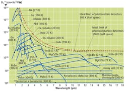
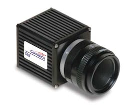
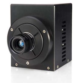
To compare different IR technologies, a figure of merit known as detectivity is used (see Fig. 1). This is a value of the signal-to-noise ratio (SNR) of the imager normalized for its pixel area and noise bandwidth. As can be seen, the detectivity of materials such as InGaAs used in shortwave-infrared (SWIR) cameras is far higher than that of IR cameras that use microbolometer devices, although the operating wavelength of SWIR devices is more limited. In specifying its SU640HSX-1.7 RT 640 × 512-pixel InGaAs Camera Link-based device (see Fig. 2), Sensors Unlimited - Goodrich ISR Systems provides a detectivity figure of 2.5 × 1013 cm √Hz/W at a wavelength of 1.55 µm and an exposure time of 33.2 ms.
However, when IR detector materials are used in camera systems, the rate-independent variable of detectivity cannot be used to directly compare the performance of the cameras because factors such as pixel size and output bandwidth directly affect performance. Instead, to determine the sensitivity of their IR cameras, manufacturers specify the noise equivalent temperature difference (NETD). Although this value cannot be used to compare different detector material technologies (as in Fig. 1), it provides a measure of camera sensitivity.
Noise equivalent temperature
Specified in degrees Celsius or, more commonly, in degrees Kelvin, NETD is a value of the temperature difference detected by the camera that produces a change in output signal intensity equal to the root-mean-square (rms) noise of the system. Thus, NETD specifies the minimum detectable temperature difference obtained by the camera.
Uncooled bolometric detectors exhibit NETDs between 30 and 200 mK; quantum-detector-based cameras that use materials such as HgCdTe (MCT) or InSb (MWIR) can be as low as 10 mK. To compare the different sensitivities of cameras that use these different materials, lenses with the same aperture must be used because this will directly affect the sensitivity of the camera. Thus, to properly compare cameras, the NETD of a camera must be specified with its operating temperature and the f/# of the lens that is used.
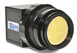
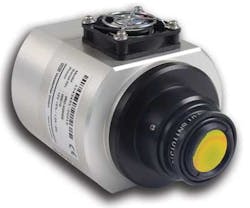
Various companies offer microbolometer-based cameras with a number of different interfaces and image formats. Based around the GigE interface, the Atom 1024 from Sofradir-EC offers a 1024 × 768-pixel microbolometer array with 17-μm pixels, a 30-Hz frame rate, and an NETD of 50 mK (see Fig. 3). Another example is the IRC-640GR from VDS Vosskühler (recently acquired by Allied Vision Technologies), a GigE-based camera that uses an uncooled 640 × 480-pixel-based imager that can achieve 24 frames/s and an NETD of 80 mK (see Fig. 4).
Increased sensitivity
To increase the sensitivity of their cameras, many manufacturers—especially those who produce devices to detect in the midwave- (MWIR) and longwave-infrared (LWIR) spectra—cool the IR devices in their cameras, which reduces the amount of thermal noise.
Several methods can be used, including thermoelectric, cryogenic, and mechanical cooling techniques. This has the effect of increasing the sensitivity; however, it also changes the spectral response of the imager (refer to Fig. 1).
In the design of its Xeva-2.5-320 SWIR camera, Xenics has used a 320 × 256-pixel HgCdTe focal plane array that features a spectral response from 0.85 to 2.5 μm. Achieving a frame rate up to 200 Hz, the camera is offered with Camera Link and USB 2.0 interfaces and uses a four-stage Peltier cooler to increase sensitivity (see Fig. 5).
Sensitivity of IR cameras can also be increased by choosing the appropriate lens. Here, a number of different materials are used to fabricate such lenses (see “IR lenses maximize detector potential,” Vision Systems Design, May 2005). Although specific lens materials will be dictated by the spectrum to be imaged, the aperture of the lens used is also important.
For example, if a low-sensitivity detector such as a microbolometer is deployed then a very fast lens (with a wide aperture) will be required. FLIR Systems specifies an f/1 lens for use with its Tau 640, a vanadium-oxide-based microbolometer camera capable of imaging the 7.5–13.5-μm spectrum and achieving sensitivity less than 50 mK at NTSC frame rates.
However, using such wide-aperture lenses limits the depth of field that can be obtained by the imaging system. More sensitive detectors based on MCT, for example, may not require lenses faster than f/2, although slower lenses are available.
Spatial resolution
Understanding the sensitivity of a specific IR camera is part of the selection process, but system developers must also determine what spatial resolution they need to achieve when specifying cameras.
Like visible-based systems, the spatial resolution of IR cameras is determined by the pixel size of the imager used. In quantum-based imagers, however, these pixel sizes are limited by diffraction. Since the diffraction-limited spot size (D) is mathematically formulated as D = (2.44) λ × (f-number), it is obvious that to detect a LWIR wavelength of 6 μm with an f/2 lens requires a pixel pitch of approximately 29 μm. Thus, the maximum spatial resolution that could be attained with such a camera would be approximately 60 μm (due to the Nyquist criterion).
Thermosensorik uses an MCT-based detector in its CMT-640L camera to image the spectrum from 8 to 9.4 μm. The camera, which employs 16 × 16-μm pixels, has a sensitivity less than 25 mK when an f/2 lens is employed. To image longer wavelengths from 7.7 to 11.5 μm, Sofradir-EC’s SSC-320VL uses a 320 × 256-pixel MCT detector with pixels sized 30 × 30 μm.
As expected, this is far larger than the pixel pitch used in visible-light cameras because the wavelength of IR is longer than that of visible light. Although many camera manufacturers may employ IR detectors that use smaller pixel sizes than is theoretically needed, the smaller pixel pitches will oversample the signal and not result in increased resolution. Because of the diffraction limit, the detectors used in SWIR, MWIR, and LWIR have respectively larger pixel sizes and increasingly lower spatial resolution capabilities.
When deploying IR cameras for inspection applications, the properties of the object to be examined must also be fully analyzed. Like with cameras used in visible-light applications, the IR radiation that is emitted from an object and can be detected by an IR camera depends on the properties of the material. In visible applications, where light is reflected from a specularly reflective object, changing the lighting conditions using a dome light, for example, can reduce the glare. In IR applications, however, the emitted IR radiation usually cannot be controlled and depends on the emissivity of the object or how it absorbs and emits IR energy.
Company Info
FLIR Systems Portland, OR, USA
Sensors Unlimited - Goodrich ISR Systems Princeton, NJ, USA
Sofradir-EC Fairfield, NJ, USA
Thermosensorik Erlangen, Germany
VDS Vosskühler (now part of Allied Vision Technologies) Osnabrück, Germany
Xenics Leuven, Belgium


