LEADING EDGE VIEWS: 3-D Imaging Advances Capabilities of Machine Vision: Part I
Engineers in the medical field were some of the first to identify the advantages of 3-D imaging, which led to the birth of x-ray computed tomography (CT) systems and nuclear magnetic resonance imaging (MRI) scanners. With the advent of high-performance imagers and inexpensive processors, those working across a swath of industries have recently recognized the benefits of adopting 3-D imaging technologies.
Systems for 3-D imaging are becoming prevalent in biometrics, with the development of 3-D face and fingerprint scanners, and in civil engineering applications where time-of-flight (TOF) scanners are deployed to create 3-D models of the interior and exterior of buildings. Engineers developing vision systems for industrial applications have also recognized the benefits of 3-D, and today, numerous pattern recognition and feature-based geometric systems are being used to automate industrial inspection processes.
Capturing images
Several ways exist to capture and process 3-D images. In single-camera implementations, objects of known size and dimensions can be imaged from an arbitrary angle, after which their most likely position in 3-D space can be determined. However, most people will be more familiar with 3-D imaging techniques that use multiple cameras. In these systems, it is not necessary to know the dimensional information of the object, simply the relative position of the cameras.
One alternative to the dual-camera approach is to use structured light techniques. A digital projector or a structured light source is used to illuminate the object. 3-D images are then reconstructed by capturing and interpreting the reflection of the structured light from the object.
Time-of-flight systems can also be used to reconstruct 3-D images by either directly or indirectly measuring the time it takes a light pulse to leave a sensor head, reach a target object, and return to the sensor.
Sensor technologies
Sensor technologies used in 3-D imaging systems can be considered either passive or active. In active systems, light is projected into a target scene, and a 3-D reconstruction is based—at least in part—on the reflection of the light back to the sensor. In passive systems, ambient light is used to illuminate the object.
3-D imaging systems can also be categorized as those that use line-of-sight scanners or cameras or those that use the principle of triangulation. In a line-of-sight camera, a sensor makes a measurement down a line of sight, whereas in a triangulation system, two cameras capture images of a scene from two different angles. While both passive systems and active systems can employ triangulation techniques, line-of-sight systems are all active.
Stereo vision
The most common form of stereo vision system uses two cameras displaced horizontally from one another. Together, these obtain two different views of a scene from which a 3-D image can be reconstructed (see Fig. 1a).
Images of an object (shown as a red letter C) are imaged by a pair of cameras (cameras A and B) whose fields of view (FOVs) are highlighted by a pair of overlapping triangles. While camera A views the image in its right-hand FOV, to camera B, the object appears on the left side of the FOV.
In these vision systems, the two images must be rectified to ensure that they are both aligned along the same vertical axes of each camera. This rectification process involves a transformation of each image plane such that pairs of conjugate epipolar lines become collinear and parallel to one of the image axes (see Fig. 1b).
Of equal importance is parallax: the displacement or difference in the apparent position of the object when it is viewed along two different lines of sight. This is measured by the angle of inclination between these two lines. Parallax is important because it is used by the system to measure the distance to the object.
Figure 2 demonstrates the concept. Here, two objects—objects C (highlighted in red) and D (highlighted in blue)—have been placed in the FOVs of both cameras.
From camera A's perspective, the blue object is to the right of the red object, whereas from camera B's it is on the left. Because the blue object has a larger parallax than the red object, it can be inferred that it is closer than the red object to the camera pair. Therefore, by making such parallax measurements on the objects in a scene, the distance from the cameras can be determined and a 3-D image of a scene can be reconstructed.
One example of a stereo camera pair that is commercially available is the Bumblebee2 from Point Grey Research (Richmond, BC, Canada). Point Grey's designers were careful to ensure that the sensors in the system were mechanically aligned to within one half-pixel of each other, essentially resolving the issue of epipolar rectification.
The tasks of determining the parallax of the objects in the FOV and generating 3-D image data are not handled by the camera directly but on a host PC. So, although the camera does not process the images directly, the mechanical design of the camera ensures that captured images are epipolar rectified.
Using a PC to handle this data processing has both advantages and disadvantages. Although doing so allows the system developer to choose various computational means of stereo-matching, some computational resources will be required.
Accuracy limits
Accuracy limits of stereo vision systems are a function of two important parameters: the radial width of the camera pixels and how far apart the cameras are spaced (see Fig. 3).
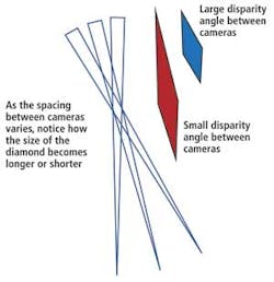
Consider the FOV from a single pixel in both cameras A and B. At the point at which the FOVs intersect, a diamond is created. The difference between the front of the diamond and the back of that diamond indicates the depth error.
The smaller the distance between the back and the front of the diamond, the more accurately the stereo camera system will estimate depth. Similarly, the higher the resolution of the imagers used in the cameras, the narrower the FOV will be of each of the pixels making the system more accurate.
To increase the accuracy of a system, the two cameras can be placed at different distances. As the spacing between cameras varies, the size of the diamond intersection created will become longer or shorter (see Fig. 4). If the cameras are close together, the diamond created by the intersection of the FOVs of the two pixels will form an elongated shape (shown in red). But if the cameras are moved further apart, the diamond will be less elongated (shown in blue). Therefore, the further the cameras are apart, the more accurately the system should estimate distance.
Imaging software
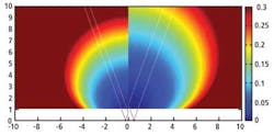
Using software developed at the University of Kentucky, it is possible to create a map (see Fig. 5) in which the length of the diamond created from a pair of 800-pixel-wide cameras spaced 1 m apart with 40° wide FOVs are color-coded as a function of distance. Unsurprisingly, the further away from the sensors, the less accurate the system becomes as the size of the diamond gets longer and longer.
The cyan-colored circle in the middle of the map (see Fig. 5, left) has a depth accuracy of 0.1 m, because the distance between the front and the back of the diamond is 0.1 m. If the spacing between the cameras is now reduced to 0.5 m, at 8 m away from the cameras the error increases to 0.2 m (see Fig. 5, right). In other words, the error is inversely proportional to the camera spacing, so the closer the cameras are, the less accurately range can be estimated.
The source code to generate these charts was written in MATLAB from The MathWorks (Natick, MA, USA) and is available to download from http://lau.engineering.uky.edu. Using the software, parameters of a stereo vision system such as the FOV, sensor size, and camera spacing can be modified and a chart generated to enable the developer to understand how such changes will affect the accuracy of a system.
In Part II of this three-part series, Daniel Lau will describe how active stereo systems can perform accurate 3-D reconstructions on scenes with low texture areas and smooth surfaces.
Vision Systems Articles Archives


