IR Cameras Take Aim at Machine-Vision Applications
Andrew Wilson, Editor
Today, the majority of cameras designed for machine-vision and image-processing systems operate in the 390-to-750-nm visible spectrum. Taking advantage of the numerous CCD and CMOS imagers that operate in this spectrum, large numbers of companies now supply cameras with different resolutions, formats, processing capability, and interfaces to address these applications.
Despite this, there are specific machine-vision and image-processing tasks that may not be accomplished using visible wavelengths. These include agriculture sorting and inspection, web inspection, semiconductor analysis, environmental monitoring, and defense-related applications.
IR characteristics
When choosing a camera for these applications, system developers must consider the resolution, speed, quantum efficiency, imager type, and camera interface specifications commonly supplied by vendors of visible light cameras, as well as other characteristics such as thermal sensitivity.
Since differing applications may require measuring wide or narrow portions of the IR spectrum, an understanding of the specific task to be accomplished is of great importance. The spectral characteristics of the material to be examined must be known, a task that can be performed using anIR spectrometer or a spectral radiometer. These devices allow transmission or reflectance vs. wavelength plots to be determined for the specific material.
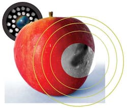
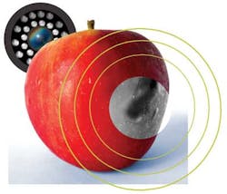
Such charts are especially useful for determining the type of detector array that must be used in the imaging system. For example, in his article "Detection of bruises on apples using near-IR hyperspectral imaging," Renfu Lu used an imaging spectrograph from Specim to measure the reflectance spectra from good apple tissue and both new and old bruised fruit over a spectral region between 900 and 1700 nm.
The reflectance from the new bruise was consistently lower than that from the normal tissue over the entire spectral region. The difference in reflectance was greatest in the region between 900 and 1400 nm. Above 1400 nm, the difference in reflectance between the bruised and unbruised tissue decreased, and the spectral images had higher levels of noise with low reflectance. This reflectivity between 900 and 1400 nm was then measured using data from an IR-based camera fromGoodrich ISR Systems–Sensors Unlimited to discriminate between bruised and good apples.
Transmittance and reflectance
Others have also studied transmission and reflectance plots for a variety of materials. Most noticeably, engineers at Inframetrics (nowFLIR) point out that when the goal is to study objects that are normally transmissive such as plastic films, care must be taken to measure the part of the spectrum where there is low transmission. In this area the film will appear opaque.
For polyethylene plastic film this region is approximately 3.4 μm, requiring the use of a shortwave- or midwave-IR (SWIR or MWIR) camera. To specifically isolate this region in the spectrum, an IR bandpass filter at this frequency will eliminate other frequencies of higher transmittance, avoiding the effect of imaging through the object (see "Broadening IR Applications through using spectral filters").
Transmission spectra for other types of films have been studied by companies such as Ircon. Samples of transmission spectra from numerous films such as polyester, polyurethane, and polystyrene supplied by plastics manufacturers indicate that for a 1-mm cellulose acetate film, there are only a few absorption bands where the transmission value is low (see Fig. 1). Since these appear in the regions at approximately 5.8, 7.3, 8.0, and 9 μm, choosing a camera that is sensitive in the MWIR or longwave-IR (LWIR) spectrum may be required (see "Plastic Film Measurement").
Emissivity values
While the transmission or reflectance vs. wavelength plots are useful in determining the specific wavelength and detector that must be used to image a specific object, the amount of energy emitted from any object will depend on its emissivity, or the ratio of energy radiated by the object to energy radiated by a blackbody at the same temperature.
Emissivity factors are important to understand since material such as oxidized aluminum may exhibit low emissivity values of 0.1, while black platinum may have values as high as 0.9. The emissivity of a material will vary as a function of temperature and surface finish; so too will the amount of radiation detected by the imager.
Whileemissivity tables can be obtained from numerous vendors including Omega Engineering (Stamford, CT, USA), such values only provide a rough guide as to the emissivity of a material. For more accurate measurements, a pyrometer such as those from Pyrometer Instrument Co. (Windsor, NJ, USA) must be used. This is especially important in thermography applications where incorrectly interpreting the emissivity of an object can lead to incorrect temperature measurement applications (see http://bit.ly/AzZF50).
Detector types
The detector type used in the IR camera is also an important consideration. Generally, these detectors can be classed into thermal and quantum devices. Both types of detectors absorb IR radiation; however, thermal detectors such as microbolometers absorb this radiation in the 7.5–14-μm MWIR band, heat the detector material, and change its electrical resistance. Microbolometer-based cameras such as those from FLIR andLumasense are most commonly employed in handheld devices for applications such as building and electrical inspection. These types of devices do not require cooling, but their sensitivity and response time are lower than that of quantum detectors.
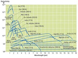
For their part, quantum detectors generate free electrical carriers through interaction of photons and bound electrons. Such detectors employ indium gallium arsenide (InGaAs) or mercury cadmium telluride (MCT) materials and offer higher wavelength-dependent sensitivity and faster response times; they may or may not be cooled to provide more accurate measurements.
To compare the spectral responses of these detectors,Hamamatsu has developed a Technical Information article entitled "Characteristics and use of infrared detectors," which can be found at http://bit.ly/xChcpd. The response characteristics can be used to determine the type of sensor that can be used to meet the needs of a specific application (see Fig. 2).
Camera sensitivity
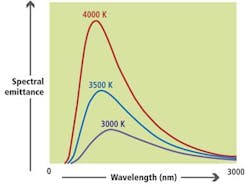
Since the amount of energy emitted from an object is temperature dependent, the higher the temperature of an object, the higher the spectral radiant energy that will be emitted (see Fig. 3). Changes that are too small to be distinguished from the background noise of the system will not be detected; measuring the noise equivalent temperature difference (NETD) provides a measure of the sensitivity of the system. Uncooled microbolometers have NETD figures of 80 to 200 mK, and cooled quantum InGaAs or MCT detectors are more sensitive with NETD values of approximately 10 mK.
To increase the sensitivity of cameras that use low-sensitivity detectors, fast lenses with wide apertures are required. Although this may increase the sensitivity of the camera system, it will limit the depth of field that can be imaged. Another way to increase the sensitivity of the camera is by cooling the sensor using thermoelectric or cryogenic cooling.DRS Technologies' Zafiro 640 Micro, for example, is a 640 × 480-pixel MCT-based camera that employs a cryogenic cooler. Although the latter method adds size, weight, and expense to IR cameras, it is especially useful in systems that operate in the LWIR spectrum because at these wavelengths, higher f-number lenses may be required to increase the achievable depth of field.
Spatial resolution
Just as with cameras that operate in the visible part of the electromagnetic spectrum, spatial resolution is dependent on the pixel size of the imager and the quality of the lens used. Like visible detectors, IR detectors are diffraction limited and thus those used in SWIR, MWIR, and LWIR have respectively larger pixel sizes and increasingly lower spatial resolution capabilities (see "The Infrared Choice," Vision Systems Design, April 2011).
However, as Andrew Bodkin ofBodkin Design & Engineering (Wellesley, MA, USA) points out in a Letter to the Editor, taking into consideration both the spot size and modulation transfer function (MTF) of the lens provides a better measure of system performance.
Many IR cameras, especially those used in thermography, must image scenes where large amounts of IR radiation from an object may saturate the image. In such cases, IR camera companies such as FLIR and Xenics use a technique known as super-framing to increase the dynamic range of the final image (see "Super-framing increases the dynamic range of thermal imagers," Vision Systems Design, February 2012). Xenics' MWIR Onca camera, for example, stitches frames with different integration times into one super-frame with a resulting higher dynamic range.
Although deciding which IR camera meets the needs of a specific application may be more complex than choosing a visible-light camera, the benefits of using such devices has influenced their popularity for specialized industrial inspection applications. Just as specifying cameras for visible-light applications requires understanding of how correct lighting can affect captured image quality, a thorough knowledge of the spectral IR response of parts must be understood before choosing an IR camera.
Vendors of IR Cameras
Allied Vision Technologies
Stadtroda, Germany
DRS Technologies
Parsippany, NJ, USA
FLIR
Wilsonville, OR, USA
Sensors Unlimited— Goodrich ISR Systems
Princeton, NJ, USA
Hamamatsu
Bridgewater, NJ, USA
Ircon
Santa Cruz, CA, USA
Lumasense
Santa Clara, CA, USA
Sofradir EC Inc.
Fairfield, NJ, USA
Specim
Oulu, Finland
Xenics
Leuven, Belgium
For more information on companies supplying IR cameras, visit the Vision Systems Design Buyer's Guide (http://bit.ly/KzRzRA).
Vision Systems Articles Archives


