LEADING EDGE VIEWS - 3-D Imaging Advances Capabilities of Machine Vision: Part II
In the most commonly used stereo vision systems, two cameras are displaced horizontally from one another to obtain two differing views of a scene. Using the image data, a 3-D image can then be reconstructed. Mappings of common pixel values between the two images must be found, the distances between these common values determined, and a depth map created.
Stereo pixel-matching algorithms are widely used to extract depth information from stereo image pairs. To compare the effectiveness of new and existing stereo-matching algorithms, engineers use sets of image pairs known as the Middlebury stereo data sets.
Stereo datasets
Figure 1 shows a stereo pair that is part of the Middlebury stereo data set. To develop a stereo-matching algorithm that can create a 3-D image from the two images, software must find each of the objects in the scene—such as the nose of the bear—from both cameras. While this may seem trivial, it is often complicated when pixels from one object in a camera's captured image are hidden behind other objects in the scene.
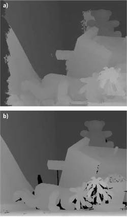
On the Middlebury web site, common stereo-matching algorithms are ranked in terms of their performance. The results of using one of the best algorithms that has been developed to perform stereo matching is shown in Fig. 2a. The brighter the gray level in the image, the closer that object is to the camera sensors.
The image in Fig. 2b has been produced using a structured-light approach rather than a stereo vision system. This offers algorithm developers a way to compare the effectiveness of their stereo algorithms with what might be considered an ideal result.
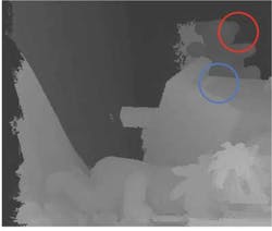
Stereo-matching algorithms perform effectively when boundaries exist between two objects. The red circle shown in Fig. 3, for example, highlights where the side of the pink teddy bear is sitting in front of a white background. Clearly, this particular stereo-matching algorithm performs effectively at identifying the boundary between those two regions.
However, the algorithm is not as successful where no clear boundaries or textures exist. The area highlighted by the blue circle in Fig. 3 demonstrates a particular case. This part of the image shows a white surface area on the front of a bird house. Because some shadow is visible, some degree of matching between the two cameras can be performed. However, at the front of the bird house, where the image is white, there is no texture or detail that allows the algorithm to definitively match a particular pixel in camera A's image with one in camera B's image.
The fact that such algorithms work very well on edges but poorly in smooth regions with no texture is a common problem in stereo vision. This is referred to as the dense stereo problem. To solve this, some developers have written algorithms that can make an intelligent guess as to how the pixels should be matched. However, such algorithms may be computationally intensive and may not work in a uniform fashion across entire images.
Computationally demanding
The computational demands of running iterative stereo vision algorithms to accurately produce a 3-D image of a scene are a particular challenge for developers of real-time systems. In the development of an autonomous robot, for example, it may not be possible to dedicate enough computational resources to iteratively reprocess data sets. What is needed is a system that can make a fast estimate of the 3-D image depth.
Such real-time systems have already been developed. Figure 4 shows an example of an image-processing system that was created to enable a vehicle to autonomously navigate a road. The image in Fig. 4a shows the video captured by the 3-D image pairs, while the image in Fig. 4b corresponds to an estimate of the stereo depth map.
This system was developed by engineers at Stanford University as part of the 2004 Grand DARPA Challenge, the goal of which was to build fullyrobotic SUVs to navigate a desert track outside of Las Vegas, NV. During the system development phase, researchers took high-resolution images of the course. The optimal driving surface was then calculated based upon the stereo depth map acquired by the stereo camera pair. Interestingly, all the vehicles that competed used similar sensor systems, although the different design teams chose to place them at different locations on the vehicle.
Active stereo
One technique that can perform accurate 3-D reconstructions even on scenes with low texture areas and smooth surfaces is active stereo vision. These systems also employ two cameras but use a projector to create texture in areas that may have none.
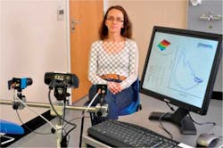
One example of a system that uses this technique has been developed by UK-basedPneumaCare (Cambridge, UK). The company's Structured Light Plethysmography (SLP) technique used in its PneumaScan system operates by first projecting a grid pattern from an LED-based digital light projector (DLP) onto a patient's chest area (see Fig. 5). Two digital cameras capture the corner features of the checkerboard grid, and two sets of 2-D points are created from the images.
A software-based triangulation method then identifies each of the grid locations, and from these, a 3-D representation of the chest and abdominal wall surface is recreated. A reconstruction is then performed on the data set to remove unwanted areas such as limbs that might have entered the field of view during an examination.
Changes in the volume of the chest are calculated in software from the reconstructed virtual surfaces and can be plotted graphically in real time as the patient breathes. Because the lung is the only compressible part of the torso, the system can calculate the flow of air into the lungs, i.e., how the volume of the torso changes over time.
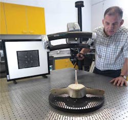
Another category of stereo vision systems that operates on similar principles is white-light scanners. The Stereoscan3-D fromBreuckmann (Meersburg, Germany) is a two-camera system coupled with a light projector (see Fig. 6). The two cameras are mounted onto a carbon-fiber arc frame, capturing images of an object while it is illuminated by striped patterns generated by the projector.
What differentiates this design from the PneumaCare system is that the projector projects not just one but a series of sequential patterns onto the object. These structured-light patterns are then captured, the results analyzed, and the dimensions of the object computed.
Like any 3-D system, accuracy is partly controlled by the spacing between the cameras. For shorter-range scanning, the two cameras in the system can swivel inward although the resulting decrease in camera spacing results in less depth accuracy.
Passive stereo working as active stereo
In passive stereo vision systems, depth accuracy is limited by the spacing between the cameras with larger spacing, making correspondence matching more difficult and computationally complex. However, passive stereo vision systems can operate at long ranges with varying lighting conditions and can, for instance, work well in bright sunlight.
To minimize the likelihood of incorrect pixel matching on surface areas that have no texture, it is also possible to couple a projector to such systems to create an active stereo vision system, but this creates its own challenges—the most important of which is to overcome any issues associated with viewing the pattern in bright ambient light.
If a single pattern is projected onto the object to be imaged, then the process can be executed in real time. While multipattern active stereo vision systems have the advantage of higher accuracy, they tend to be slower since objects cannot be moved during the scanning process.
In Part III of this three-part series, Daniel Lau will explain how structured-light scanners can be used to produce high-resolution 3-D scans.


