3-D Scanner Images Dental Molds
Andrew Wilson, Editor
Anyone who has ever endured major dental work will be familiar with the process used to take dental impressions. After placing a viscous liquid alginate in a dental impression tray, a technician presses the tray onto the patient's teeth until the liquid sets to form a solid negative impression. This impression is then employed to make a plaster cast of the teeth, which is used to study the best way of fabricating dentures or crowns.
To ensure that the prosthetic teeth are precisely made, these plaster casts are 3-D scanned and the 3-D data generated used to create aCAD model of the plaster cast. The models can be manipulated using CAD packages to simulate the placement of prosthetic teeth. After successful modeling and simulation, models of newly created prosthetic teeth are sent to a CNC machine to produce the final prosthetic product.
Scanning teeth
To date, a number of 3-D scanner companies such as 3Shape AS and smart optics providers such as Sensortechnik have built products to address this market.
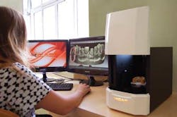
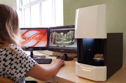
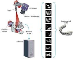
While such products are effective, engineers at the Velasco Group recognized the need to reduce the scanner cost. The company has expanded its activities into the dental market with the introduction of its XCAD scanner (see Fig. 1). Marketed by XCADCAM, the scanner was conceived by Leandro Velasco, director of the Velasco Group. Rather than use fringe pattern projection or multiple cameras in the design, the scanner incorporates a structured-light system that illuminates the mold as it is rotated on a 9-cm-diameter platen (see Fig. 2).
To perform a 3-D scan, the operator first places the mold onto the platen in the scanner. After initializing the system, both the laser and camera are moved across the mold. The structured laser light illuminates the mold in they-z plane and 500 reflected laser light profiles are captured by a 0.3-Mpixel USB 2.0 Firefly camera from Point Grey Research. These data are used to create a surface model of the mold that contains a data cloud of approximately 200,000 points. After the initial scan, the mold is then rotated with two degrees of freedom to allow optimal positioning, and successive scans are performed. By repeating this process between 8 and 10 times in selected positions, any occlusions in the mold generated from any single scan can be eliminated.
Cost reduction
In assessing how to reduce the design cost, engineers at Velasco opted to use low-cost stepper motors from Lin Engineering to move both the camera and laser head and perform platen rotation with a stepper motor controller.
After developing the mechanical concept for the scanner, Velasco turned toAqsense to aid in the optical design of the system. According to Ramon Pallí, general manager of Aqsense, the choice of a stepper motor resulted in a ±5% error that would not initially provide the 20–50-µm accuracy required. Fortunately, such errors are repeatable and can be accurately measured by scanning a known 3-D calibration object. Thus, by storing the measured error data, positioning errors in subsequent stepper motor positions can be compensated. By reducing the error in this way, the 20–50-µm resolution becomes achievable.
Usingstructured laser light in the system also introduced a degree of speckle noise generated by multiple laser reflections of the same frequency with different phases and amplitudes resulting from a specific point on the mold. Because such reflections produce a resultant wave whose intensity varies randomly, this generates spatial noise. To compensate for this, successive image data of the reflected laser light captured in the Firefly camera are used to average the speckle noise.
Scheimpflug principle
One of the major design accomplishments of the XCAD scanner is the use of theScheimpflug principle. In many imaging systems, the lens and image are parallel so the plane of focus is parallel to the lens and image plane. However, in the XCAD scanner, the mold to be imaged is never parallel to the image plane; thus using a standard lens system would result in the camera only being in focus along a line.
However, as Theodor Scheimpflug realized, by mounting the lens at an angle to the plane of the sensor, the in-focus plane can be changed from being perpendicular to the camera's sensor to being at an angle to it (see "Lens Designs Tackle Novel Vision Applications," Vision Systems Design, July 2011). By placing a lens holder at approximately 5° and using a standard lens, the full surface of the plaster mold could be imaged successfully.
Using this type of optical system did present Aqsense's designers with challenges. Since the lens system is not perpendicular to the image plane, standard algorithms could not be used to compensate for any lens distortion that may occur in the optical path. So Aqsense developed a specialized algorithm to compensate for any asymmetric distortion. This algorithm has now been incorporated into the company's 3D Shape Analysis Library (SAL3D) that is used for point-cloud processing of image data.
System calibration
Of course, before any part can be scanned, the XCAD scanner must be calibrated. To accomplish this, Aqsense developed a 3-D ceramic object approximately 150 mm long × 42 mm high × 90 mm wide. Once placed in the scanner, Aqsense's Angular Calibration software based on the company's SAL3D Angular Metric Calibration Tool allows the calibration of alaser-triangulation system such as that used in the XCAD scanner, where the camera and laser are rotating about an axis.
Once the reference object is scanned by the system, calibration parameters can be stored and used to reference captured data of the dental mold. During the scanning of each dental mold, the resulting 500 images of the laser stripes are transferred over the camera's USB interface to the host computer. The software processes the images to obtain clouds of around 200,000 points.
Using an exclusive software development from some building blocks of SAL3D, each of the individual point clouds are then combined into a single closed mesh that eliminates any occlusions that may have occurred in each separate image dataset. From the final dataset, a single 3-D surface can be generated and exported from the system as a Standard Tessellation Language (STL) file.
The data can be manipulated on any standard PC using any of the CAD software packages that are employed in the production of fixed prosthetics such as bridges and crowns.
Company Info
3Shape AS
Copenhagen, Denmark
Aqsense
Girona, Spain
Lin Engineering
Morgan Hill, CA, USA
Point Grey Research
Richmond, BC, Canada
Sensortechnik
Bochum, Germany
Velasco Group
São Paulo, Brazil
XCADCAM
São Paulo, Brazil


