Vision System Inspects Hydraulic Components
Earl Yardley
Earth-moving equipment requires immense energy sources to provide the power it needs for civil engineering work. While motors power the hydraulic pumps that move the machines' components, control valves provide the operator with the precise feel and control required to perform trenching, rock breaking, and demolition. These same motors are also used in cranes, wheel loaders, and general construction equipment.
Although the designs of such motors, pumps, and control valves have existed for decades, their method of manufacture has changed rapidly over the last few years to address the need for more modular designs and just-in-time manufacturing.
Constructing pumps using modular components results in a variety of pumps, each with its own unique characteristics. It is therefore critical for the manufacturer to check that all components are the correct type before constructing the pump; once built, it is difficult and costly to rework the unit if a fault is later detected.
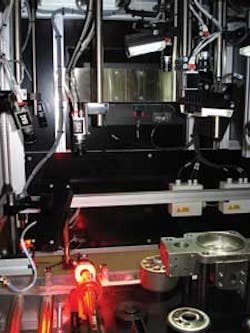
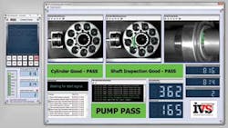
Kawasaki Precision Machinery (www.kpm-usa.com), a leading manufacturer of hydraulic motors and pumps, approached Industrial Vision Systems to develop a machine-vision system that could inspect pumps as part of a semi-automated assembly process (see Fig. 1).
Moving fixtures
Previous manual inspection of the pump subassemblies did not require precise positioning or presentation of the parts because an operator would manually handle the part. However, the vision system requires that each component and all its variants be presented repeatedly in the same position in a controlled lighting environment.
Each part must be presented on a fixture to the vision system with all the components fitted onto one large fixture design, so multiple cameras can be used to view all the components in one inspection position. These parts include the pump case, shaft, cylinder block, valve plate, and valve cover. In the design of the fixture, numerous part variants need to be accommodated so each part can be automatically inspected when these are present.
The travel board fixture is driven into the inspection station on a roller conveyor, with the fixture locked in place during the inspection process. The vision system does not release the fixture to continue down the production line if a failure is identified. Instead, it is pulled back to the entry operator to rework the fixture board.
System design
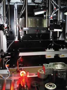
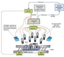
Built from an extruded aluminum framework, the machine incorporates a central roller feed conveyor system, and incorporated into the conveyor are pneumatically driven stops. Six digital Gigabit Ethernet cameras from NeuroCheck (www.neurocheck.com) connected to an industrial PC running NeuroCheck's machine-vision software are employed to inspect the parts (see Fig. 2). Optics are specified to give the correct field of view and positioning for the cameras. The lenses are all from Pentax and range from wide-angle 8.5 mm (for the larger components) to 35 mm for the shaft inspection. All lenses are fixed-focus, manual iris lenses with the ability to lock once the defined settings are established.
Cameras, optics, and lights are mounted from individual doweled fixtures, which are mounted inside the main inspection canopy. The system is shrouded to eliminate the effects of ambient lighting.
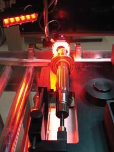
The lighting for the vision system was designed and implemented following thorough investigations and trials on known good and bad parts. The final selected lighting solution is a combination of high-intensity white LED area light units with built-in polarizers, combined with red LED ringlight units for inspection of the shaft end (see Fig. 3). The lighting units were manufactured by DCM Sistemes (www.dcmsistemes.com), based on extensive testing completed in the IVS laboratories during the design phase of the project. The red LED ringlight unit gave direct lighting to the very edges of the shaft to provide contrast on the teeth.
The fixture carrier is manufactured from black anodized aluminum with a matte finish to offer a contrast in placement on some of the components. Cycle time for the inspection process is not critical as the manufacture of these pumps is relatively slow; only one part every few minutes is required to be inspected.
Imaging algorithms
Machine-vision inspection functions are selected from standard routines available in the NeuroCheck software and deployed to check the five main components on the fixture board in sequence.
The main shaft inspection application is designed to check the number and type of teeth on each shaft to confirm it is the correct type. NeuroCheck's rotating template-matching software allows templates to be found within the defined regions of interest irrespective of their rotational position. The teeth are then counted and mapped based on their size and type. This ultimately allows NeuroCheck to confirm the shaft matches that requested by the line programmable logical controller (PLC) system (see Fig. 4).
The complete manifest information is transferred from the master PLC to the machine PLC via Ethernet. This information is then used to open the relevant inspection routines within NeuroCheck to confirm the parts match the manifest.
The main pump inspection and the associated valve plate and cover checks are accomplished by matching the captured image with a trained template. Due to the precise positioning of the products on the board no rotational movement of the templates is required.
After the software has examined all the characteristics of all the components, it determines whether the pump manifest meets all the tolerances that have been specified, or whether the parts must be reworked or rejected.
Statistical data
As the image-processing system inspects and categorizes the devices, and only allows good products to continue down the production line, it also collects statistical data during the inspection process. After the machine has checked several batches of product, the data are used to determine how any changes in acceptable tolerances will affect the yield of the product.
In addition, the system provides ongoing statistical process control of the products being manufactured for later analysis. Images of every product can also be saved and allocated against their serial numbers to allow images of every product leaving the factory to be stored if required. The latest NeuroCheck 6.0 vision system software provides built-in statistical process control displays to show historic trending in real time. For example, the last 100 units processed are shown on the screen with line-graph tracking of the upper and lower limits and current measurements.
The vision system provides a method for 100% inspection of the pump product prior to assembly of the complete unit. This allows a modular production approach to be adopted and later flexibility to be accommodated. Ultimately, it provides Kawasaki's customers with the reassurance that the product is being built to the required specifications and that the quality offered by Kawasaki is of the highest standard.
Earl Yardley is with Industrial Vision Systems (IVS) Ltd. (www.industrialvision.co.uk).
Company Info
DCM Sistemes www.dcmsistemes.com
Industrial Vision Systems (IVS) Ltd. www.industrialvision.co.uk
Kawasaki Precision Machinery www.kpm-usa.com
NeuroCheck www.neurocheck.com
Vision Systems Articles Archives
