Pharmaceutical stoppers inspected by vision
R. Winn Hardin, Contributing Editor
View the Image Gallery>>
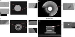
Pharmaceutical closures, such as molded coated or uncoated rubber stoppers, are manufactured under certified clean room conditions in accordance with FDA regulations to ensure that they meet exacting quality requirements. However, since no manufacturing process is perfect, defects can occur and parts can become contaminated with various foreign particles such as fibers during the several stages of the production process.
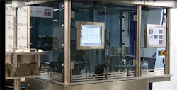
To ensure that no parts are shipped to a customer with such defects, Simac Masic & TSS (Heerlen, The Netherlands; www.simac.com) has developed an automated vision inspection system that has been deployed at the facilities of pharmaceutical stopper manufacturers. In addition to inspecting the top, bottom, outside and inside of the stoppers for defects up to 100μm square, the system also detects any imperfections in the shape of the parts at a rate of up to 12 stoppers per second.
Machine design
Designed in a modular fashion, the machine vision system continuously conveys the stoppers through two vision stations and one metal detection station after which the parts are either accepted and bagged for shipment or rejected and scrapped.
To orient the parts in a consistent fashion, stoppers are deposited from a hopper into a vibratory bowl feeder which feeds them out onto an accumulation track with the top of the stoppers facing downwards. The linear track conveys the parts along a line towards a rotating mechanical vacuum wheel with hooked ratchet-shaped pockets which protrude from its outer rim. When the parts reach the end of the track, the pockets sequentially pick the parts off the accumulation track and hold them in place on the wheel through a vacuum applied through small apertures in the pockets. The wheel is then rotated counterclockwise towards the first of the vision inspection stations.
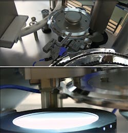
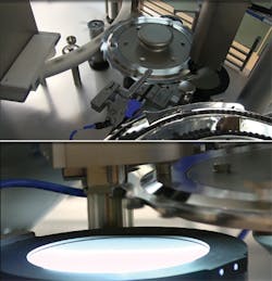
At the first vision station, the top and the steep sidewalls of the bottom of the hollow plug in the pharmaceutical stoppers are inspected for defects. To do so, the product is illuminated by a high-intensity LED cloudy daylight strobe situated beneath the wheel which effectively freezes the motion of the part to eliminate motion blur. As the part is illuminated, a 1600 x 1200 pixel color CCD camera under the wheel is triggered to capture an image of the top of the stopper (which is facing downwards on the wheel). At the same time, the bottom of the part (which is facing upwards on the wheel) is illuminated by a Xenon strobe light, after which a second 1600 x 1200 pixel color CCD camera captures an image of the stopper through a fish eye lens (Figure 1).
The fish eye lens provides a long depth of field and a wide angular field of view, enabling the steep sidewalls of the hollow, centrally-located well section of the stopper to be "unwrapped" and imaged. As before, the acquired image is then transferred over an Ethernet interface to a MX80 Series image processor from Datalogic (Telford, PA, USA; www.datalogic.com) where the image is analyzed for defects.
Should any of the parts fail the two inspections that are performed while the stopper is on the wheel, a pneumatic ejector situated above the wheel blows them off the wheel and into a reject hopper. Those parts that pass both the inspections continue to be rotated on the wheel until they reach a second larger rotating FDA-approved wheel located beneath the smaller one.
Further inspections
While the cameras mounted above and below the wheel are effective at imaging the top and bottom of the parts, the sides of the parts must also be inspected to ensure that they are not contaminated with any foreign particles. This would be impractical to achieve while the parts are on the wheel, since the sides of the parts would be obscured by the ratchet-shaped pockets that hold them. Hence, further vision inspections must be carried out at a second inspection station.
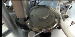
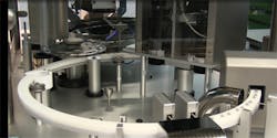
To move a stopper to this station, the vacuum applied to a pocket on the wheel is removed, and the stopper is deposited onto the track of the larger wheel situated beneath it (Figure 2). The larger wheel is rotated clockwise by a set of smaller planetary-flanged wheels mounted on servo motor driven shafts that engage with a rim projecting out from the inside diameter of the larger wheel. Prior to inspection by the third of the vision inspection stations, the parts pass through a V-shaped aperture that channels them onto the center of the wheel, ensuring that they are all consistently located.
The second vision inspection station comprises a set of five 1600 x 1200 pixel CCD cameras housed in a cabinet that capture and image the stopper from four sides and its top (Figure 3). To do so, the parts are illuminated by an LED strobe dome light chosen for its ability to uniformly radiate the entire surface of the stopper, enabling all its curved surfaces to be imaged.
Due to the space limitations in clean room manufacturing environments, the four cameras that image the sides of the product are mounted vertically, rather than horizontally. The four 1600 x 1200 pixel color CCD cameras capture an image of the sides of the products through right-angled prisms beneath the lenses. While the bottom of the stopper had been inspected previously while the part was held on the vacuum wheel, a fifth 1600 x 1200 pixel CCD color camera captures another image of the bottom of the stopper through the center of the LED dome light. This undistorted image allows the image processing software to determine whether any defects exist on the end sealing flange of the stopper.
To enable the cameras to capture high-contrast images with low geometrical distortion, each of the five cameras are fitted with a telecentric lens. This enables the system to image a variety of different shaped stoppers from a single manufacturer without the need to reconfigure the camera positions or settings, since the depth of field provided by the telecentric lenses means that it is no longer necessary to determine the exact distance between the stopper and the lens prior to image acquisition.
Once the five images have been acquired at the second station, they are transferred over an Ethernet connection to three further Datalogic MX80 Series image processors. The first of the quad core processor systems processes images from one pair of horizontal images of the part, a second processes the second pair, while the third system processes the images of the top of the stopper.
Following the vision inspection at the second station, the wheel rotates the stoppers through a metal detector to ensure that the parts have not been contaminated with any ferrous material during production. The parts are then rotated until they reach a reject station. If a contaminated part has been identified by either the third vision station or the metal detector, the part is pneumatically ejected from the ring into a pipe where the parts are collected.
Parts that pass the inspection processes continue to travel along the ring until they reach a collection station where they are ejected from the ring and collected into one of two bins. Further downstream from the collection station, a photoelectric sensor detects whether any of the stoppers remain on the ring. If they do, the machine can either be stopped, or a second pneumatic system can be used to blow the parts off the ring into a reject bin.
System software
To build the image processing software for the system, Simac Masic & TSS employed Datalogic's Vision Program Manager (VPM). The VPM software is used to first determine regions of interest in the image which indicate the likely position of the part. Pattern matching is then performed over the ROIs to ascertain the location of the top, bottom, or sides of the stopper. The images are then filtered to enhance specific features on the image, after which a blob detection tool is deployed to detect any regions in the image caused by fiber contamination or spots that can differ in brightness or color compared to the areas surrounding them (Figure 4).
To enable an operator to visualize and interact with the system, two HMIs were developed. The first of these was built using Datalogic's Control Panel Manager (CPM) and enables all of the images captured during the inspection process to be logged and displayed to an operator on a flat panel display interfaced to the PPT MX80 Series image processors.
The second HMI runs on an Industrial PC. It was developed using LabVIEW software from National Instruments (Austin, TX, USA; www;ni.com) and performs the task of capturing and storing all of the data relating to the sequence of inspection activities that have taken place on the stoppers. These parameters are displayed to an operator on a second flat panel display (Figure 5). To control the machine, a PLC from Beckhoff Automation (Verl, Germany; www.beckhoff.com) was used in combination with a product tracking and tracing system.
Because manufacturers may need to inspect a variety of stoppers of different shapes and sizes, the LabVIEW HMI also enables an operator to select which type of stopper is to be inspected through the second touch screen display. Once the stopper type has been selected, all the inspection and control programs relating to that specific part are automatically downloaded to the Datalogic's vision processor and the Beckhoff PLC.
The HMI also allows operators to interrogate the system to generate a statistical analysis showing the pass/fail rate of the parts that are being inspected, enabling management to determine whether any manufacturing issues may have occurred in the upstream manufacturing processes.
Companies mentioned:
Beckhoff Automation
Verl, Germany
www.beckhoff.com
Datalogic
Telford, PA, USA
www.datalogic.com
National Instruments
Austin, TX, USA
www.ni.com
Simac Masic & TSS
Heerlen, The Netherlands
www.simac.com
