Andrew Wilson, Editor
Machine vision systems are now commonplace in many factory automation systems. In building these systems, developers must carefully evaluate the type of product to be inspected and how the proper choice of illumination and optics can be used to increase the contrast of captured images. In doing so, the throughput of the machine vision system will be improved since less time will be spent on processing the captured images to extract relevant information.
Before embarking on any specific illumination choice for any particular application, however, it is important to know what type of illumination system should be used. Today, many manufacturers offer LED illumination products in various types of configurations depending on the type of product to be inspected. For example, while flat diffuse surfaces may best be illuminated using a ring-light, the flat specular objects may require diffuse on-axis lights or cloudy day illuminators to increase the contrast of features to be inspected.
While the choice of such lighting is important, so is the choice of the wavelength of light to illuminate the part. Which frequency to use will be dependent on the properties of the part since these will determine which wavelengths will be reflected and absorbed. By selecting a wavelength that matches the feature of interest to be extracted and choosing a light source of the same color, the feature will appear brighter and vice versa.
Rather than experiment with multiple wavelengths, systems developers can choose to use optical filters to perform this task. By illuminating an object with a broad spectrum white light for example, band-pass filters can be placed in front of the camera to select a specific wavelength that offers the optimum contrast. In this way, the correct choice of illumination wavelength can be determined inexpensively. To ease the task of choosing the correct filter, companies such as Thorlabs (Newton, NJ, USA; www.thorlabs.com), Midwest Optical Systems (Palatine, IL; www.midopt.com) and Edmund Optics (Barrington, NJ, USA; www.edmundoptics.com) offer kits with a variety of different types of filters. Other filter manufacturers such as Chroma Technology (Bellows Falls, VT, USA; http://www.chroma.com/) specializes in custom filter solutions, providing in-house engineering and production capabilities.
Neutral density
Optical filters also prove useful in reducing luminous intensity, increasing system resolution, eliminating glare, separating colors, color correction and, of course, increasing the contrast of the object being imaged. In machine vision applications such as arc welding inspection, it may be necessary to reduce the amount of light being captured by the camera. In such applications, neutral density (ND) filters can be used to reduce all the wavelengths of light equally. Using such filters, cameras with larger apertures can be deployed reducing the depth of field of the scene and thus better separating the object image from its background.
Many manufacturers specify the characteristics of these filters in terms of their optical density (OD) – the optical power transmitted through the filter - which is given mathematically as OD = -Log10 (Im/In), where Im is the measured intensity and In is the incident intensity. Thus, for example, a neutral density filter with a fractional transmittance (Im/In) of 0.5 will have an optical density of 0.3. Some ND filters are specified over the just visible region of the spectrum, and do not proportionally block all wavelengths of UV or IR. This may be important in machine vision systems that employ CCD or CMOS imagers that may be sensitive in both the UV and IR regions.
Because of this, a number of companies offer such ND filters especially tailored for machine vision and scientific applications. The TECHSPEC UV-NIR neutral density filters from Edmund Optics, for example, can attenuate light from the UV to the NIR (190-1700 nm) and are available in 12.5, 25, and 50 mm diameter sizes and optical densities of 0.3, 0.5, 1.0, 1.3, 1.5 and 2.0.
Band-pass filters
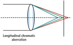
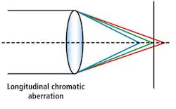
While neutral density filters are used to reduce the light impinging on the sensor of the cameras, band-pass filters can be used to increase image contrast while at the same time selectively passing wavelengths within a certain range. Image contrast is effectively increased because the axial or longitudinal chromatic aberration of the optical system will be reduced. In systems that exhibit such axial chromatic aberration, the refractive index of the lens varies slightly as a function of the wavelength. Since the refractive index of the lens is greater for blue light (shorter wavelengths) than red light (longer wavelengths) different wavelengths will be focused at different focal points along the axis (Figure 1).
Systems designers can compensate for this effect by choosing achromatic or apochromatic lenses to focus two or three wavelengths of light, respectively onto the same plane. Using less expensive lenses, band-pass filters that eliminate the UV and IR spectrum can also be used to reduce this type of chromatic aberration. In many imaging applications, such band-pass filters are used to enhance the contrast of a specific feature within an image.
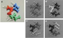
If the color of this feature is known, the proper choice of lighting and filter allows a monochrome camera to be used to increase the contrast of the desired object (Figure 2). Here a number of green, blue and red band-pass filters from Midwest Optical Systems are used to filter an image of push pins illuminated with white light. As can be seen, each of the colors can be selectively highlighted using these filters. An added benefit of using monochrome cameras over color cameras in such applications is the increased resolution that can be obtained.
Today, most color cameras developed for machine vision systems use monochrome imagers with Bayer filter arrays that pass red, green and blue light to selected pixels. To obtain a color image, a Bayer interpolation algorithm is then performed (often in the FPGA) of the camera. This interpolation results in a somewhat lower quality color image with a loss of resolution and edge artifacts.
Using a monochrome camera with a color filter, however, no such interpolation is required and the resolution of the captured image will be improved, all other parameters being equal. In specifying these band-pass filters, filter manufacturers provide their customers with a number of important characteristics including the optical density (OD), the peak transmission, the center wavelength, the bandwidth of the filter and its blocking range.
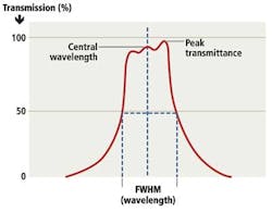
While the peak transmission provides the wavelength at which the maximum light is transmitted, the bandwidth is the difference between the half-power wavelengths or full width at half maximum – FWHM - (Figure 3). Band-pass filters from Schneider Optics (Hauppauge, NY; USA; www.schneideroptics.com), for example, are available in the 465 nm to 865 nm range with an FWHM from 50 nm to more than 100 nm, in sizes 10-74 mm in diameter.
Chroma Technology also manufactures filters with square-wave transmission profiles which offer the same peak transmission over a range of wavelengths. These filters typically provide 95% transmission with very high levels of rejection of unwanted wavelengths (≥ OD6).
Reducing glare
While the use of specialized lenses or band- pass filters can be used to decrease the chromatic aberration and increase the contrast of objects in an image, the use of specialized lighting such as cloudy day illuminators can reduce the effect of the direct high intensity light reflections and glare that may result when on-axis illumination is used. This glare can also be reduced by employing optical polarizing filters in the system's optical path.
By placing a polarizer in front of the light source, the light will become linearly polarized. Light directly reflected from the object will also be linearly polarized while any diffuse light will be reflected un-polarized. Thus, by placing a second polarizer in front of the camera, only the diffuse reflected light will be imaged, reducing glare. While the use of such polarizers will attenuate direct reflections from specular surfaces, un-polarized light passing through a perfect polarizer will attenuate 50% of the light passing through it and reduce the intensity of light on the object being imaged. Reflected light will also be attenuated depending on the structure of the object being imaged.
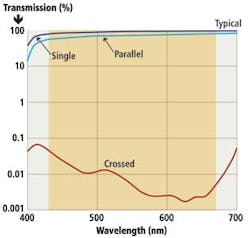
Such linearly polarized filters are specified by the percentage of light they transmit. Data sheets for these polarizers show how the polarizers can be used in single, parallel and crossed configurations. Here, light transmission for a single polarizer shows the percentage of light passing through a single polarizer while a parallel configuration will employ two polarizers in which the axis of polarization of each is aligned in the same direction.
If the axis of polarization of the two polarizers are crossed at 90 degrees, much less light will pass through the optical system (Figure 4). In this example, the transmission chart of a visible polarizer from Newport (Irvine, CA; USA; www.newport.com) is shown in single, parallel and crossed configurations.
Acknowledgements
The author would like to thank Barry Warzak, President of Midwest Optical Systems and Mariann Kiraly, Senior Account Manager of Midwest Optical Systems with their help in writing this article.
Companies mentioned
Chroma Technology
Bellows Falls, VT, USA 05101
www.chroma.com
Edmund Optics
Barrington, NJ, USA
www.edmundoptics.com
Midwest Optical Systems
Palatine, IL, USA
www.midopt.com
Schneider Optics
Hauppauge, NY, USA
www.schneideroptics.com
Thorlabs
Newton, NJ, USA
www.thorlabs.com
Vision Systems Articles Archives
About the Author

Andy Wilson
Founding Editor
Founding editor of Vision Systems Design. Industry authority and author of thousands of technical articles on image processing, machine vision, and computer science.
B.Sc., Warwick University
Tel: 603-891-9115
Fax: 603-891-9297
