3D vision system inspects thermoformed plastic cups at high-speed
Nate Hinkle
Manufacturers of plastic beverage and dairy containers used in the food industry must produce thousands of products per hour. Thermoforming machines that produce the products heat a plastic sheet that is then formed into a specific shape using a molding press.
After such products are trimmed, they are labeled using a process known as dry offset printing. This uses a printing plate to transfer images to a rubber pad that in turn transfers them onto the surface of the plastic cups. After printing, the ink is then cured using a high-intensity ultraviolet (UV) light.
Like thermoforming machines, dry offset printers can produce finished cups at rates as high as six hundred cups per minute. Any defects in the surface of these cups cannot be tolerated since this may affect the integrity of the seal which is placed on each cup after it is filled. Such defects may then affect the quality of the food or beverage placed in the cup resulting in spoiled product, line stoppages, product recalls and damage to the reputation of the manufacturer.
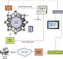
To ensure that defective cups can be detected and rejected at high-speeds, Industrial Control (Zeeland, MI, USA;www.industrialcontrol.com) was tasked to develop an automated system that could be installed on a dry offset printer from WIFAG-Polytype (Fribourg, Switzerland; www.wifag-polytype.com) and integrated with the rejection mechanism already in place (Figure 1).
In operation, stacked thermoformed cups are first de-stacked and placed onto a Ferris wheel mechanism that is composed of eight evenly spaced carriers. After the cup is placed onto the first carrier, it is rotated though a number of separate stages for heat treating, cooling, printing and UV curing. At particular stages, each cup is rotated on a mandrel as they move around on the Ferris wheel mechanism.
3D imaging
Inspection of the parts needed to be performed while the part was rotating at high speed. In the presence of a high power, broad-spectrum curing light, part defects produced little to no contrast. Because of this, traditional camera-based vision systems proved to be inadequate. Instead, the system uses a 3D Gocator 2330 smart sensor from LMI Technologies (Delta, BC, Canada;www.lmi3d.com).
To check for dimensional defects, the Gocator is installed before the parts are cured with UV light. As each part is rotated, a red 635nm laser line light from the Gocator is projected onto the rim of the cup. Reflected laser light is then digitized by a 1.3M pixel camera embedded in the Gocator. After this reflected light is captured, the Gocator determines the peak position of the reflected laser line profile. The system measures a line profile of the part as it is rotated by the offset printing machine, resulting in up to 126 line profiles for each part.
These line profiles are then used to determine both the width and shape of the rim of each cup. To measure the width of each cup, each line profile is plotted and the highest in-plane value (that represents the top of the cup) is compared with the leftmost value (that represents the inside edge of the cup). Since every cup will not be perfect, this width will vary as the cup is rotated under the field of view of the Gocator. Should these width measurements then fall outside an acceptable limit, the cup is then rejected at the correct index station. Acceptable parts move through the indexing system to the final stage and are then ejected.
Rim quality
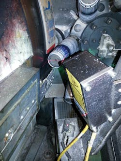
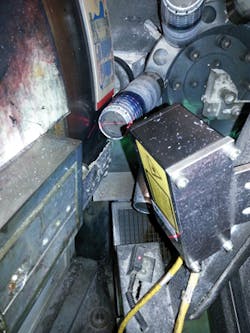
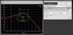
This line profile is also used to determine the quality of the rim of each cup. Figure 2 shows both a good cup (a) and a bad cup (b) with a malformed edge while Figure 3 shows the line profile that is returned from the 3D system. To determine the profile of the corner of the cup, a bounding box (in yellow) is first placed around the part of the line profile that corresponds to the reflected laser profile from the edge of the cup. A best fit circle is then computed around this profile and the radius of the circle determined. This radius then provides a value that represents the curvature at the edge of the cup. Should this value fall outside predetermined limits, the cup is again rejected at the next indexing station.
To trigger this reject mechanism, the Gocator sends a 2.5ms signal to a 750-881 programmable logic controller (PLC) from Wago (Germantown, WI, USA;www.wago.us). This PLC is then used to trigger a second PLC from Siemens (Munich, Germany; www.siemens.com) at the dry offset printer that actuates the rejection mechanisms. Both the Gocator and Wago PLC are in turn interfaced to an Ethernet switch from Turck (Plymouth MN, USA; www.turck-usa.com).
Industrial control
To monitor the status of the system, an industrial touch panel computer from AIS (Irvine, CA, USA;www.aispro.com) is interfaced to the Ethernet switch. Since the Gocator has a built-in web-based user interface, a Google Chrome-based browser running on the industrial touch panel can be used to set up, program and visualize data from the device over the Ethernet connection. Similarly, a web-based browser page served by the Wago PLC can be used to program and monitor pass/fail rates of the system.
To allow the system to be programmed and monitored remotely, the Turck Ethernet switch is also interfaced to a Cosy 141 industrial VPN appliance from eWON (Nivelles, Belgium;www.ewon.biz). This can be accessed over the Internet using eWON's eCatcher software. In this way, all the functions of the PLC and Gocator can be set-up and monitored remotely and securely.
Thermochecker systems have been installed on eleven systems at five production facilities in the USA and Canada. A video of the system in operation can be viewed at http://bit.ly/Wqv7Hx.
Nate Hinkle,Sales and Applications Engineer, Industrial Control (Zeeland, MI, USA; www.industrialcontrol.com)
Companies mentioned
AIS
Irvine, CA, USA
www.aispro.com
eWON
Nivelles, Belgium
www.ewon.biz
Industrial Control
Zeeland, MI, USA
www.industrialcontrol.com
LMI Technologies
Delta, BC Canada
www.lmi3d.com
Turck
Plymouth MN, USA
www.turck-usa.com
Wago
Germantown, WI, USA
www.wago.us
Vision Systems Articles Archives


