Vision system inspects engines in-line
A robotically-controlled vision system can inspect components fitted to several ranges of diesel engines during a critical stage in the engine assembly process.
Dave Olson
Automotive engines are assembled sequentially as they are conveyed through a number of production stations. During the process, cylinder blocks are fitted out with pistons and crankshafts. Additionally, valves and rocker arms are mounted onto cylinder heads. Once the two sub-assemblies have been constructed, they are joined together with mechanical linkages such as push rods prior to any further assembly operations.
Although many stages in the assembly process are automated, a number of inspection procedures have traditionally been performed manually to ensure that specific mechanical components and linkages in the engine are positioned correctly after the two sub-assemblies are joined together. Now, however, vision systems are playing an important role in automating these processes too, eliminating any potential errors that may have previously occurred due to operator fatigue.
When one diesel engine manufacturer needed a system specifically to perform such an automated inspection of critical components fitted to its range of diesel engines, it turned to machine builder RedViking (Plymouth, MI, USA and Raleigh, NC, USA; www.redviking.com and www.redviking.co.uk) that developed a fully automated system to meet this task. Although just three models of engines were produced on the company's assembly line, the number of variants of those models meant that the system needed to be flexible enough to accommodate them all.
Having evaluated the possibility of using a contact measurement system or a laser scanner, RedViking ultimately chose to build a vision inspection system based around a smart camera attached to a robotic arm (Figure 1). During the inspection process, the robot moves the camera around the engine assembly to capture images of critical components in the engine while avoiding any other components that might obscure the view of the camera. Having done so, the system analyzes the images to determine whether the critical components are present and are positioned correctly. The results of the inspection are highlighted to an operator during the procedure on a human machine interface.
Engine assembly
In a diesel engine, linear motion is transformed into rotational motion by pistons connected to a crankshaft in the cylinder block. As each piston moves during the strokes of the engine, a pair of inlet and exhaust valves on the cylinder head open and close, enabling air to be drawn into the engine and exhaust gases to escape.
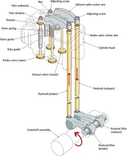
The opening and closing of the valves in the engine is controlled through linkages from the camshaft. As the camshaft rotates, a mechanical pushrod transfers the reciprocating motion generated by lobes on the end of the camshaft to a rocker arm mounted on the cylinder head (Figure 2).
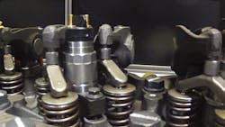
The rocker arm compresses and releases springs on the inlet and exhaust valves through a mechanical crosshead, or bridge. Positioned on the top of the valve stems, the crosshead enables one rocker arm to actuate two valves simultaneously, while a crosshead socket fitted to the top of the crosshead acts as a pivot to allow the crosshead to open and close the exhaust and inlet valves in a predetermined sequence (Figure 3).
During the assembly of the engine, the crossheads and the crosshead sockets are positioned on top of the valves in the cylinder head, after which the rocker arm is placed on top of the crosshead socket which holds them in place. As the cylinder block is joined to the cylinder head, the pushrod from the crankshaft is positioned such that a ball at the end of the rocker arm fits into a socket at the end of the push rod.
Due to the loose fit of the crossheads, crosshead sockets and push rods at this stage in the assembly process, it is vital that all of the components are inspected to ensure that they are present and that none of them have become misaligned, since any unacceptable tolerances could potentially lead to engine failure.
Automated inspection
Traditionally, the process of inspecting the components was performed manually. To do so, an operator would look down into the engine to visually determine whether the mechanical components were located correctly and to flag those that were not. However, this highly labor intensive procedure was also prone to errors.
The vision system developed by RedViking replicates the earlier manual inspection criteria, while doing so in more repeatable, less error prone fashion. Due to the number of variants of engine produced at the assembly plant, the system had to be first taught to identify the locations of crossheads, crosshead sockets and push rods from all of the variants on the assembly line.
During the teaching process, an 800 x 600 pixel In-Sight 7000 vision system from Cognex (Natick, MA, USA; www.cognex.com) placed on the end effector of the six-axis robot was moved to specific positions around an engine. There, images of pairs of crossheads and crosshead sockets mounted on the top of each cylinder, and the socket housing the ball at the top of the push rod, were captured in a sequential fashion.
The images of the key components were analyzed by a set of vision software tools that come pre-installed in the Cognex In-Sight vision system running on the In-Sight 7000 vision system. Cognex' In-Sight Explorer spreadsheet was used to configure the vision tools, to analyze the data created by them and communicate the results of the analysis between the In-Sight vision system and a CompactLogix PLC from Allen Bradley (Milwaukee, WI, USA; www.rockwellautomation.com) running the system.
Using the Cognex PatMax pattern match tools in the In-Sight Explorer software, the system was trained to search for patterns within the two images and identify specific patterns in the images representing the crossheads, crosshead sockets and push rods. By presenting the vision system with numerous acceptable and unacceptable positional variants of the components for any each engine, it was possible to define specific numerical ranges in which the position and orientation of the components would be acceptable.
During the inspection process, the Cognex PatFind vision system software tools could then be used to identify the components and match those with models in the system. After finding a match, the system could determine whether the orientation of the parts fell within the acceptable limits previously defined, or whether the measured parameters deviated from them.
Software solution
When an engine arrives at the inspection station on the assembly line, the plant network sends the specific type and variant of the engine to the system, which is then displayed on a nearby human machine interface running on an Allen-Bradley PanelView. Once this data is received, the CompactLogix PLC lowers an enclosure over the engine to limit the amount of natural light entering the station.
The CompactLogix PLC, which is programmed with specific positional information associated with each particular engine, then instructs the robot arm to move the Cognex In-Sight camera on the robot end effector to the first of several positions adjacent to the engine (Figure 4). Once there, it captures a side view image of the crosshead and crosshead socket associated with the first cylinder.
Having done so, the In-Sight software finds a known reference point from which the location of the crosshead sockets and the crossfoot can be determined. The Cognex PatFind pattern matching tools then ensure that the parts are present, in the correct position and oriented properly. To do so, the PatFind tool analyzes the geometric information from each of the parts and the known reference in the image and calculates their spatial relationships.
The PLC moves the robot end effector along the engine, sequentially measuring the orientation of each of the crosshead and crosshead sockets as it does so. Each image is processed in turn until all of the components have been inspected. Once the system has completed the crosshead and crosshead socket inspection tasks, the CompactLogix PLC moves the robot arm to the other side of the engine where images of the sockets of the push rods are sequentially captured and analyzed in a similar fashion.
Visualizing the results
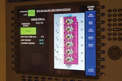
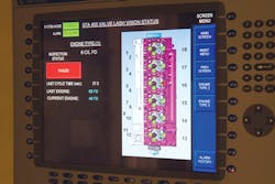
To enable an operator to visualize whether any of the components in the engine had passed or failed the inspection procedure, RedViking created a schematic representative view of each engine as it might appear to an operator looking directly down upon it. During the inspection procedure, the representative view, which highlights the position of the valve crossheads, cross head sockets and sockets, can be viewed on an Allen-Bradley PanelView HMI which provides pass/fail information for each inspection.
Should the In-Sight vision processing software running on the camera determine that a specific component is within acceptable limits, the In-Sight Smart camera sends a pass signal to the PLC. Based on the known position of the camera at the point at which the image was captured, the PLC then instructs the Allen-Bradley PanelView HMI system to highlight the area which has passed the inspection with a green circular marker on the representative view of the engine. If any components fall outside those limits, a fail signal is sent to the PLC which instructs the Allen-Bradley PanelView HMI system to highlight the area in red (Figures 5a and b).
If all the components pass inspection, the engine proceeds down the production line where further assembly operations are performed on it. If a single failure is detected by the system, the engine is sent to a technician to correct the failure and re-insert the engine back in to the assembly line.
The images of each of the components in the engines captured by the vision system are also saved to a local PC over an Ethernet interface, and are tagged with the inspection results, as well as identifying information (such as time, date, and engine serial number). While these can be used by an operator to help identify any possible causes of failure, they can also provide a means by which engineers can verify whether any engines later identified as defective were caused by any of the inspected components moving out of tolerance at a later stage in the assembly process.
Dave Olson,
Controls Engineer Leader,
RedViking,
Raleigh, NC, USA
(www.redviking.com)
Companies mentioned
Cognex
Natick, MA, USA
www.cognex.com
RedViking
Plymouth, MI, USA
www.redviking.com
www.redviking.co.eu
Rockwell Automation/Allen Bradley
Milwaukee, WI, USA
www.rockwellautomation.com


