Imaging takes to the skies
An airborne imaging system has been developed to capture multispectral images of the earth's surface for a variety of applications in agriculture, forestry and hydrology.
Professor Jens Bongartz
Traditionally, aerial photography has been an expensive process that required the use of cameras mounted in aircraft or helicopters. More recently, however, a new class of aircraft called rotocraft has emerged that offer a more cost-effective alternative.
The first of these-the gyrocopter-uses an unpowered rotor to develop lift, and an engine-powered propeller to provide thrust. The second-the quadcopter-is a multi-rotor helicopter whose lift is generated by vertically-oriented propellers.
While the cost of deploying either a gyrocopter or a quadcopter equipped with imaging systems are both substantially less than using a helicopter for aerial image acquisition, the gyrocopter has certain benefits. First, its payload can be greater than that of the quadcopter, and its endurance-or the time it can remain in the air-is longer.
Recognizing these inherent advantages, researchers at the Fraunhofer Institute for High Frequency Physics and Radar Technologies (Remagen, Germany; www.fhr.fraunhofer.de) have teamed up with colleagues at the Koblenz University of Applied Sciences (Koblenz, Germany; www.hs-koblenz.de) to develop the AMLS imaging system, a unit that can be mounted on board a gyrocopter and deployed for airborne imaging applications in agriculture, forestry and hydrology.
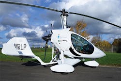
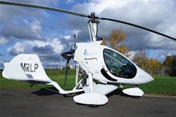
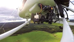
The manned two-seater gyrocopter chosen for the task can fly between 30-150km/hr at an altitude of between 150-1500m. Equipped with an imaging payload of up to 100kg, the gyrocopter can remain in the air for up to five hours, during which time it can cover a distance of around 500km (Figure 1).
In the development of the imaging payload used onboard the aircraft, a number of commercial hardware and software products were chosen. These enable the pilot to guide the aircraft along a specific flight path, to automatically trigger a camera (or cameras) to capture images of the terrain below the aircraft, and to enable the stored images (which are tagged with GPS coordinates) to be stitched together off-line into a single orthogonal image mosaic.
The first task in the development of the system, however, was to build a stabilized platform onto which a single D800E 36MPixel camera from Nikon (Tokyo, Japan; www.nikon.com) with a 35mm lens could be mounted. This enabled a number of aerial images to be captured at a spatial resolution of less than 5 cm/pixel as the gyrocopter flies 300m above the ground. Having done so, the effectiveness of the imaging system and the image stitching software could be evaluated.
To enhance the stability of the platform in flight, the camera was mounted on a gimbal which was mechanically decoupled from the airframe to prevent the propagation of vibrations from it to the camera. In addition, the gimbal was designed to compensate for variations in roll and pitch which the gyrocopter experiences under normal operating conditions. To do so, two sensors measure the pitch and roll of the gyrocopter and the results from the measurements are used in a closed loop feedback system to control two electric motors to stabilize the movement of the camera in those two axes.
Flight plans
Having built the stabilized platform for the camera, the next challenge was to develop a system that would enable an operator to draw up a flight plan for the aircraft, and trigger the camera to capture images-and their associated GPS coordinates-at appropriate times during the flight.
To do so, the system uses off-the-shelf software from Aeroscientific (Blackwood, Australia; www.aeroscientific.com.au). The company's Windows-based Flightplanner software allows a user to select an area of terrain for which a flight plan is required, to select the camera used to capture the images and define the various parameters for the aerial image acquisition, such as the size of the overlap of the images, the flying height, ground pixel resolution and camera frame rate.
After the flight plan has been drawn up, it is exported and used as an input into Aeroscientific's Aviatrix software. The Aviatrix graphical user interface displays a variety of information to the pilot and to the camera operator. This includes the bearing and distance to the target over a real-time moving map, the current location of the plane within the flight plan area and real-time feedback of triggered camera locations.
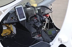
In the AMLS system, the Aviatrix software runs on a 4Sight GPm industrial computer from Matrox (Dorval, QC, Canada; www.matrox.com) with a small external control display. A ToughPad FZ-M1 from Panasonic (Osaka, Japan; www.panasonic.com) sits in front of the pilot, enabling the pilot to visualize where to navigate the aircraft during the image acquisition process (Figure 2).
Global positioning
In many traditional aerial imaging systems, GPS systems are used in conjunction with onboard Inertial Measurement Units (IMUs). While the GPS systems capture altitude, latitude and longitudinal coordinates, the IMU simultaneously record details on the pitch, yaw and roll of the aircraft at the instant each image frame is acquired. The combination of GPS and IMU data provides a more accurate means of determining the location of the aircraft when images are captured than a GPS system alone, and reduces the number of ground points needed to be processed in the images in the image stitching process.
However, IMU hardware can be expensive. To lower the cost of the AMLS system, a single Trimble (Sunnyvale, CA, USA; www.trimble.com) GPS system is used to tag the images captured by the camera. The GPS data is then transferred over an Ethernet connection to the Matrox PC where the captured images are tagged with the GPS coordinates the instant they are acquired.
In an initial test of the system, the gyrocopter equipped with the 36MPixel Nikon camera was flown at a height of 300m, capturing a sequence of 300 overlapping images (5 square kilometer in total) of the terrain beneath it along many parallel flight paths. To ensure that the images could be effectively stitched together off-line, the images were captured with an in-track overlap of 80% and a cross-track overlap of 60% to ensure that the overlapping areas of the images would contain enough detectable features.
Since the AMLS system does not use an IMU in conjunction with a GPS system, the position of the camera and its attitude can only be determined to an accuracy of +/-1m. This increases the computational task that need to be performed on the images to match key features during the image stitching process. Despite that fact, the use of commercial off-the-shelf software enabled the image processing task to be performed cost-effectively.
Structure from motion
After the flight, panchromatic image data captured by the Nikon camera were downloaded from the hard drive on the Matrox 4Sight GPm onto to an Intel 8 core workstation fitted with graphics accelerator cards from NVIDIA (Santa Clara, CA, USA; www.nvidia.com). Images were then processed using the Photoscan structure from motion software package from Agisoft (St. Petersburg, Russia; www.agisoft.com).
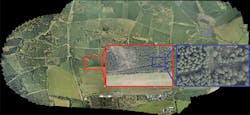
Structure from motion algorithms are widely used to build 3D models from 2D images of buildings. Here, however, the software was deployed to create ortho-rectified maps from the images captured by the camera (Figure 3). To do so, the software identifies specific features in an image such as buildings or trees, and then shifts and rotates neighboring images identified through their GPS coordinates to determine the best fit between the features found in the neighboring images.
Having proved the effectiveness of the single panchromatic system, a further system was built to capture images that could be analyzed to measure the surface temperature of rivers and lakes in Germany. This system used a Mako panchromatic camera and a Pearleye LWIR camera both from Allied Vision (Stadtroda, Germany; www.alliedvisiontec.com) that incorporates an uncooled microbolometer sensor to detect the temperature differences in the landscape (Figure 4). Both cameras were mounted on the same gimbal.
The cameras were flown in a test-flight over an open stone pit in the Blankenheim region of Germany at a height of 500m and, under control of the Aviatrix software, were triggered by the Matrox system to capture a series of images of the vegetation below. These images were then transferred to the system's hard drive over a GigE interface. After the flight, the images were downloaded to the workstation for processing by the Agisoft software.
To create an orthogonal map of the region, the panchromatic images were first stitched together and then the set of thermal images taken at the same instant in time with the same field of view were overlaid onto them (Figures 5 a, b and c).
Agricultural applications
To demonstrate the applicability of the system in agricultural applications, a further incarnation of the system was built that uses three identical Allied Vision Mako cameras - one panchromatic camera (whose images are used to create stitched orthogonal images) and two additional cameras fitted with filters that can acquire spectral reflectance measurements in the visible red and near infrared regions. From the visible red and the near infrared images, a Normalized Difference Vegetation Index (NVDI) was calculated to determine whether the imaged scene contains live green vegetation. This NVDI image can then be mapped over the stitched panchromatic image.
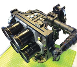
In the future, the multispectral capabilities of the imaging platform will be extended (Figure 6). A new platform-currently under development-will use six cameras mounted on a gimbal in the aircraft - one panchromatic camera and five additional cameras fitted with filters to enable specific wavelengths of light to be captured. The completed system, which may eventually be commercialized, would enable researchers to configure the system according to the specific properties of the terrain they are interested in monitoring.
Professor Jens Bongartz, Head of Department, Application Center for Multimodal and Airborne Sensors (AMLS), Fraunhofer Institute for High Frequency Physics and Radar Technologies (FHR; Remagen, Germany; www.fhr.fraunhofer.de)
Companies mentioned
Aeroscientific
Blackwood, Australia
www.aeroscientific.com.au
Agisoft
St. Petersburg, Russia
www.agisoft.com
Allied Vision
Stadtroda, Germany
www.alliedvisiontec.com
Fraunhofer Institute for High Frequency Physics and Radar Technologies
Remagen, Germany
www.fhr.fraunhofer.de
Koblenz University of Applied Sciences
Koblenz, Germany
www.hs-koblenz.de
Matrox
Dorval, QC, Canada
www.matrox.com
Nikon
Tokyo, Japan
www.nikon.com
NVIDIA
Santa Clara, CA, USA
www.nvidia.com
Panasonic
Osaka, Japan
www.panasonic.com
Trimble
Sunnyvale, CA, USA
www.trimble.com
