Using the Map-Seeking Circuit algorithm in object recognition
Using an MSC algorithm, it is possible to recognize and locate arbitrarily-shaped 3D objects in complex, cluttered scenes using 2D cameras.
David W. Arathorn
While machine vision is being increasingly used in industrial automation tasks, its capabilities are often limited, leaving many manufacturing tasks unsuitable for automation. One of the limitations of machine vision technology its inability to recognize and locate 3D objects that lack certain specific features and characteristics. Systems using cameras that return 3D images mitigate some of these restrictions (though only for objects with non-reflective surfaces which return undistorted surface coordinates), but make the problem of isolating the object of interest and matching it to some 3D model more computationally expensive.
Using a map-seeking circuit (MSC) algorithm, however, makes it possible to recognize and locate arbitrarily-shaped 3D objects in complex, cluttered scenes using simple 2D cameras. Inexpensive parallel computational hardware in the form of graphics processing units (GPUs) enables this algorithm to run at real-time rates on inexpensive PCs and even on mobile hardware.
In many applications, a single object can appear in a variety of shapes and sizes depending on the direction and distance from which it is viewed. How human beings an easily recognize such objects without apparent effort is not currently understood.
In machine vision systems, this task is complicated because an object of interest may appear anywhere within an image, rather than approximately centered on the eye's high resolution but small diameter fovea. The mathematical term for the way a 3D object forms an image in the eye is sometimes called "an image formation transformation" and this transformation is sometimes called "projection."
Mathematically, what happens in the real world is almost identical to what happens in a video game when the 3D model of an object in the scene is projected onto the viewer's screen. The problem in machine vision is the inverse of what happens in a video game since the image captured by the camera contains a 2D projection of the object of interest. Often all the machine vision system knows about that object is the 3D CAD model of that object, and that model may be one of many different models of different objects.
The problem for machine vision, in this case, is to compute which view of the model corresponds to the view of the object in the camera image when it is not known from what direction or distance that the object is being imaged, nor where in the image the object will appear. Mathematically, the image formation transformation mentioned above must be computed, except backwards, from the image to the CAD model of the object.
Rotated letters
To provide a simpler example, avoiding the complexities of three dimensions and their projection onto a 2D image plane, suppose an input image r contains several variously rotated letters in various locations and a memory template w with an upright "A" in the center (Figure 1).
To recognize the rotated "A" in the input image it is necessary to match that part of the input image with the memory template that contains the upright "A." To make this match, the tipped "A" will need to shifted to the center of the image and rotated upright. Assuming the input image is 400 x 400 pixels and the "A" is 20 x 20 pixels then, the "A" can appear in any of 3802 or 144,400 locations in the image. If it is also assumed that the "A" can be rotated in 5° increments, or 72 different rotations, then using a simple brute force approach, up to 144,400 different shifts or translations, times 72 different rotations, or over 10 million tries, will be required to place the "A" so that it will match the A in the memory template.
If it takes 1 microsecond to make each attempt, then on average 5 seconds would be required to make the match. This example ignores the possibility that the "A" in the image may be a different size from the "A" in the template and would also have to be scaled to make the match succeed.
With 3D objects, which can present different views, as occurs in most real world situations, the task becomes even more computationally expensive. This multiplication of all the possible variations is known as "combinatorial explosion" and is what makes brute force approaches to the problem impractical.
Decomposing the task
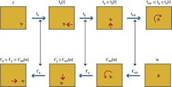
However, suppose the problem above is decomposed into three stages, each of which performs in sequence one kind of movement or transformation on the input image (Figure 2).
Notice that there are 380 possible movements to bring any location to the center along the x axis, 380 movements to bring any location to the center along the y axis and 72 possible rotations to bring the "A" to an upright orientation. This makes a total of 872 total transformations - far fewer than the 10 million required using a brute force approach. If there were a way to make the match between the "A" in the input image and the "A" in the memory template at a computational cost proportional to 872 instead of more than 10 million, then such a task becomes more practical.
This is the concept behind the map-seeking circuit (MSC) algorithm - the only known way to test the more than 10 million possible shifts and rotations at a cost proportional to k times 872, where k is a small constant (typically less that 10). The coefficient k reflects the fact that a number of iterations are usually required to reach the solution reliably, but also that each iteration requires less computation than the one before. So if the algorithm takes 15 iterations to converge, the actual cost in computation is typically between 5 and 7 times the time for the first iteration, depending on the hardware platform.
The MSC achieves this dramatic improvement in efficiency by avoiding trying all 10 million combinations of one x translation with one y translation with one rotation. Instead, the MSC forms a kind of photographic multiple exposure of all the the x translations of the input image. This multiple exposure is called a superposition, meaning a summed image of all the x translations of the input image. The cost of this is 380 operations, as discussed above. Then the MSC takes this multiple exposure or superposition and applies 380 y translations to it, forming a new multiple exposure or superposition. This second multiple exposure contains all the translations in the x and y direction of the input image. The second multiple exposure now is subjected to 72 possible rotations which are summed to form a third superposition. This superposition contains within it the exact translation and rotation which matches the memory template of the "A". However, it also contains all the other 10 million plus possibilities.
Multiple exposures
Each of these multiple exposures or superpositions might seem like a big blur, and so they are. However, because of the organization of the MSC each blur can be "taken apart" and the correct x translation, y translation and rotation can be discovered. However, to perform this, the multiple exposures at each stage must be compared with something that will determine which of the patterns (translations or rotations) that formed it are most likely to be the ones that produce the correct net or aggregate transformation of the "A" in the input image to match the "A" in the memory template.
To determine this, the memory template pattern is transformed by the opposite sequence of transformations (also known as inverse transformations) that then form multiple exposures in the opposite sequence of stages. For example, if in the path of stages from the input image to the memory template, known as the forward path, there is a 20° rotation in the third stage, then there must be a -20° rotation in the path from the memory template toward the first stage. The -20° rotation in the backward path is the inverse of the 20° rotation in the forward path.
To understand this, mathematically, the symbol t represents a transformation and its subscript says what type of transformation it is, i.e. in what stage it takes place. The forward path transformations are denoted as tsubscript. The inverse of transformation tsubscript is notated as t'subscript. For clarity, the application in sequence of transformations tx , ty and trot to the pattern r is notated trot ○ ty ○ tx(r). The operator ○ is known as the composition operator. trot ○ ty ○ tx(r) is mathematically identical to the functional notation trot ( ty (tx(r))) but is much easier to read.
The forward and backward sequences of the transformations are shown in Figure 3. The top path is called the forward path, and the lower one is called the backward path.
If the correct sequence of forward path transformations and their backward path inverses has been selected, each forward/backward pair of images matches exactly. This is crucial, because it is the basis of the selection of which transformation in each stage is the correct one. Here, it is not single patterns that are being matched but multiple exposures or superpositions of patterns in the forward and backward paths.
The property of superpositions
The mathematics behind this is rather complicated, but the principle is called the ordering property of superpositions. This makes it possible to pick with increasing probability which of the transformations making up the multiple exposure in each stage is the one required. This is performed not all at once but gradually, step by step, or iteration by iteration.
In each iteration the probability of selecting the correct transformation increases, so even if the wrong one is chosen in the first few iterations, the error of selection is corrected with very high probability in later iterations. This gradual movement toward a solution is known as convergence and is common to many mathematical procedures.
To execute this gradual selection process, a variable, q, is created for each transformation in each stage which measures how good the match between the forward path and backward path is at the current state of the convergence. Another variable, g, is then created for each transformation in each stage which controls how much each transformation and its inverse contributes to the forward and backward multiple exposures or superpositions in each stage. The q for each transformation tells the algorithm how much to change the g for each transformation during each iteration of the convergence. All the g's are initialized to 1.0 at the beginning of convergence and gradually all but one (almost always the correct one) decrease to zero by the end of convergence. In fact, the condition for ending convergence is when all but one g in each stage reaches zero.
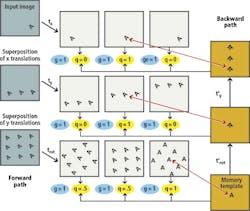
Graphically, the MSC can be shown as if it had only three transformations in each stage (Figure 4). In this example there would be 380 transformations in the first and second stages, and 72 transformations in the third. However, to simplify matters, it is assumed that there are three transformations in each stage and the state of the MSC is shown after the q's are computed during the first iteration. The figure shows the superpositions in the forward and backward paths, and the state of the q's and g's. Note that each forward transformation is compared to a superposition in the backward path, and each q is the result of this comparison.
As can be seen, the only x translation that works is the one that moved the "A" to the center. Since this matches superpositions in the backward path image, q is set to 1 and the other q's are set to zero because there is nothing to match but empty space if "A" is moved to the right side or left side. In a similar fashion, the only y translation that works is the one that moves it to the center and so that q is set to one and the others are set to zero since there are no matches above and below in the center image in the backward path. The final rotation transformation stage is more ambiguous because for each transformation there is some rotation of the "A" in the center position, but the rotation that makes the center "A" upright is the clear best match with the template "A", so its q is the greatest.
At the end of the each iteration the q's are used to update the corresponding g's. This is performed as follows. The largest q in each stage, implying the transformation in that stage producing the best match with the superposition in the backward path, leaves its corresponding g unchanged. Any values of q smaller than the largest q cause the corresponding g to decrease, so that in the next iteration the less favored transformations will be less weighted in the superposition.
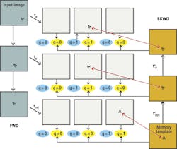
To use a photographic metaphor, it is as if the lens is only wide open for the most favored pattern in the multiple exposure and the lens is stopped down to varying degrees for the less favored patterns. The objective is to gradually dim all the patterns in all the multiple exposures until only the pattern of the correct transformation is left at full brightness. Mathematically speaking, after a number of iterations, the g's for the transformations which do not produce the best matches all go to zero, leaving only one g in each layer non-zero. These non-zero g's specify the optimal sequence of transformations. That is the final, or converged, state of the MSC (Figure 5).
Applications of MSCs
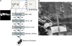
The backward path is necessary for the computation of the solution, but it also has a major benefit. Because the sequence of transformations in the backward path after convergence is the exact inverse of the transformations that maps the target in the input image to the template in memory, the backward path maps the template to the exact size, rotation and location of the target in the image. If the memory template is a 3D model, it also selects the correct projection of the model. Consequently, if a 3D model of a pig exists and an input image in which a particular view of the pig appears with other objects, the backward path projection of the pig exactly matches the view, size and position of the pig in the image (Figure 6a).
In fact, the backward projection of the model exactly overlays the target in the image, as in the infrared image of a pickup truck in a wooded scene (Figure 6b). The memory template is a CAD model of the same model pickup truck. One benefit is that this congruence of the back-projected template and the object in the image proves that the solution found by MSC is correct. For target recognition applications, the algorithm highlights for the human operator any target that is located by the MSC.
Here, the implication for industrial automation applications is that given the camera parameters (position in space, pointing direction and focal length), the 3D rotation, scale and translation parameters yielded by the MSC convergence give the position of the object and its orientation in space from a simple 2D image, even when that object is located amid other objects and clutter. If one wanted to use the information from the MSC solution to guide a robot arm to pick up the identified object, the scale determined by MSC translates into the distance, call it z, from the camera (if the size of the object and the focal length of the camera lens is known) and the location in the image translates into x and y coordinates in space.
The 3D rotation parameters give the orientation of the object relative to the camera, so the combined information, plus the CAD dimensions of the object provide the data necessary for the inverse kinematics for the robot arm and hand.
With two cameras, 2 MSCs working from the same 3D model can locate the object even more precisely. This is because the x, y coordinates of the same object in two images captured from different locations can be used to triangulate the position of the object in space if one knows the positions and focal lengths of the two cameras. This is more accurate than the single camera method because the resolution in x and y is almost always finer than the scale resolution, so the distance can be more accurately computed. Cameras that produce 3D images (e.g. LIDAR) have been used as input to MSC by matching the relative depth data from the camera with the depth (z-axis) of each rotation of the 3D model, and using the absolute depth data from the 3D image to locate the object in space.
As can be see in the two examples in Figure 6, the silhouette shape (also called the occluding contour) is sufficient to locate the object and determine its orientation. The object need not have any special computationally-convenient surfaces. While the examples shown only use the occluding contour for recognition and location, interior edges and other surfaces can readily be included.
The MSC algorithm does not care what features are used to characterize an object so long as normal image formation transformations can be applied to them. Nor does the object of interest have to have a rigid or standardized shape. MSC can be also configured to recognize articulated objects (such as human figures or military tanks) and morphable objects, such as hoses or lumps of bakery dough. This is described on the MSC website at www.giclab.com.
Public domain
The core MSC algorithm is in the public domain and open to be used by anyone. For developers, support is provided at www.giclab.com. The references section of the website lists publications on both theory and substantial implementations by the author as well as by Johns Hopkins University Applied Physics Lab (Laurel, MD, USA; www.jhuapl.edu) and Lockheed Martin Corporation (Bethesda, MD, USA; www.lockheedmartin.com).
For mathematical reasons explained on the website, the robustness and speed of an MSC-based vision system depends profoundly on the internal representation of the image and model, and this is the area in which the best performing MSC-based systems tend to be proprietary, as well as in the code to implement the MSC itself. General Intelligence Corp's GPU-hosted MSC server is to date the highest performing and most suitable for industrial automation applications. GIC is open to negotiating joint development of MSC-based vision systems for industrial automation, including licensing the GPU-based MSC server for inclusion in such systems.
Companies mentioned
General Intelligence Corp (GIC)
Bozeman, MT, USA
www.giclab.com
Johns Hopkins University Applied Physics Lab
Laurel, MD, USA
www.jhuapl.edu
Lockheed Martin Corporation
Bethesda, MD, USA
www.lockheedmartin.com
David W. Arathorn, President, General Intelligence Corp (GIC; Bozeman, MT, USA; www.giclab.com) and Assistant Research Professor, Department of Electrical and Computer Engineering, Montana State University (Bozeman, MT; USA; www.montana.edu).


