Robot vision automates connector assembly
A vision-based robotic system automates the assembly of electrical connectors for the aerospace industry.
Edwin Tan
Assembling electrical connectors for the aerospace industry is an intricate operation that has traditionally been performed manually. In the process, trained operators insert numerous metal pins, plastic insulator seal plugs, and sockets into various sizes and shapes of electronic connectors to ensure that they conform to the exacting military standards demanded by the industry.
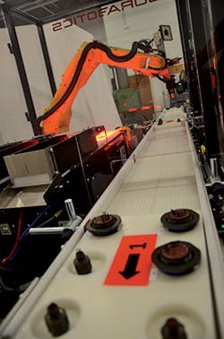
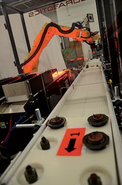
The intricate procedure is manually intensive, time consuming, expensive and prone to errors. To alleviate the need to perform such operations manually, decrease costs and increase reliability, one aerospace connector manufacturer recently tasked Durabotics (Eagan, MN, USA; www.durabotics.com) to develop a vision-based robotic assembly cell to automate the process (Figure 1).
In operation, the system conveys a pallet containing connectors into a robotics assembly cell where the contents of each pallet are first verified. An LR Mate 200iD/7L robot from Fanuc (Rochester Hills, MI, USA; www.fanucamerica.com) then sequentially removes each connector from the palette and places it onto an assembly station where the robot populates the connector with the appropriate number of pins, plastic insulator seal plugs and sockets which are picked from a set of three Durabotics Model 510 backlit shaker table style feeders. Having done so, the assembled connector is placed back into the pallet. Once all the connectors have been assembled and returned to the pallet, the pallet is then conveyed from the assembly cell.
The complexity of the assembly process was compounded by the sheer number of styles and sizes of connectors that the system was required to assemble. More specifically, the system was required to build over sixty styles and sizes of connectors. As well, each style and size of connector could have any combination of up to around 100 insertions of up to three different metal pins, seal plugs and/or sockets. This can be readily expandable to six different combinations of pins, plugs, and/or sockets with the addition of three more shaker table feeders.
To meet that need, Durabotics chose to deploy a modular system that could accommodate a variation in connector types and styles and be programmed though a PC-based Human Machine Interface (HMI) to enable it to assemble any new connector variants that might be required in the future.
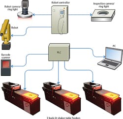
Aside from the touch screen HMI, the system comprises a master PLC which controls the operation of the machine, three further slave PLCs that control the number of parts fed onto the shaker tables, and a PC that stores detailed characteristics of each of the connectors and the operations to be performed upon them. The robot is controlled by a dedicated robotic controller with an integrated vision system trained to identify the connectors and the parts to be inserted into them at various stages during the assembly process (Figure 2).
The Durabotics custom end effector consists of three major sections. First, to capture images of the parts, a camera and ring light was interfaced to a Fanuc iRvision system. Secondly, a QC001 master side tool changer from ATI Industrial Automation (Apex, NC, USA; www.ati-ia.com) provides a vacuum, electrical and mechanical connection to four custom double-ended tools on an adjacent custom tool changer rack.
Each of the four tools on the tool rack covers a range of pin, seal-plug, and/or contact sizes. The tool uses one vacuum-actuated end-effector for part pick/place, while the opposite end contains a mechanical seating tool. Lastly, a universal gripper is used to load and unload the full range of connector bodies on the pallet.
Automated assembly
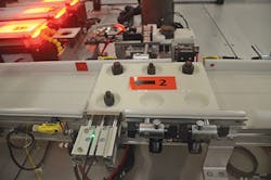
The automated assembly process begins when a pallet containing six connectors is carried into the robotic assembly cell on a conveyor under the control of a Compact Logix 1769 PLC from Rockwell Automation Allen Bradley (Milwaukee, WI, USA; http://ab.rockwellautomation.com). The pallet moves along the conveyor until it reaches a load station where a photoelectric cell is then triggered and the conveyor is halted (Figure 3).
Each pallet can contain six different types and sizes of connectors, and these can all have different combinations of pins, seal plugs and sockets that need to be inserted. Hence, before the universal gripper on the robot removes a connector from the pallet, the system must first identify the types and sizes of connectors that are present.
To do so, a bar code scanner from Keyence (Elmwood Park, NJ, USA; www.keyence.com) scans a bar code attached to the side of the pallet and transfers the pallet number over a serial interface to a PC. A custom built Visual Basic program then queries the pallet number against a Microsoft Access database file running on the PC to determine which connector styles and sizes are present in the six specific slots in the pallet. It also outputs the recipe of contacts, seal plugs and sockets that need to be inserted into each connector.
After the string of data from the PC identifying a connector type and the operations to be performed on it has been transferred to the robot controller, the arm of the Fanuc robot moves over to the first slot in the pallet. Once there, a WR 80 x 80 LED ring light from Banner Engineering (Minneapolis, MN, USA; www.bannerengineering.com) attached to the arm of the robot illuminates the connector, and an Ace acA1300 1.3Mpixel camera from Basler (Ahrensburg, Germany; www.baslerweb.com) captures its image. This image is then transferred over an Ethernet interface to a Fanuc R-30iA controller equipped with iRVision, Fanuc's integrated vision processor. The software running on the vision processor performs a geometric pattern match algorithm on the image to identify the type of connector that is located in the slot and determine its position.
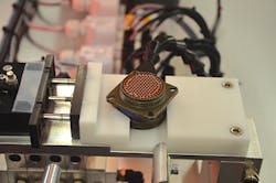
The Durabotics custom built end effector on the robot then picks the connector from the palette and places it onto a self-centering V-shaped assembly vise station where it is clamped (Figure 4). The robot controller then moves the end-effector equipped with the camera over the vise fixture, activates the ring light and captures a second image of the connector. This image is again transferred to the Fanuc vision processor over an Ethernet interface where another geometric pattern match tool is used to determine the position and orientation of the connector in the vise fixture.
Population increase
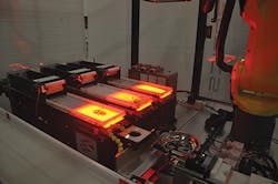
The robot then proceeds to populate the connector with metal contacts and seal plugs according to the recipe sent to the controller from the PC. To do so, the robot chooses the appropriate end-effector before picking a metal pin, plastic insulator seal plug or socket from one of three backlit shaker table feeders that shake and spread the parts apart, a process that enables the robot vision system to identify isolated parts (Figure 5).
As the robot moves over a backlit shaker table, the camera attached to the end-effector on the robot arm captures an image of all of the parts on the table. The image is again transferred to the Fanuc integrated vision processor which performs two important image processing operations.
First, the image is analyzed to determine the saturation of parts on the table. To do so, the system software running on the integrated vision processor performs a histogram of the pixel intensity values in the image. By analyzing the intensity values in the image, the system can then determine the population of parts on the table. Should the analysis reveal that the table is inadequately populated a slave PLC housed inside the table actuates a servo motor to open the gate of a hopper above the table to enable more parts to be fed onto it.
The image is also analyzed to determine which of the parts on the shaker table the robot end-effector should retrieve. To do so, a pattern match algorithm is again performed on the image of the parts. In the process, the image of each of the parts on the table is matched to a trained ideal model of the part. A score is then assigned to each one based on how well it matches the model. The part with the highest score is the one that is then picked by the robot end effector.
Part orientation
During each pick, the robot moves the part past a straightening tool to assure it is properly oriented on the end of the end-effector. A connector pin, for example, will be removed from the table at a right angle with respect to the end-effector. However, before it can be inserted into the connector it must be oriented vertically. To do so, the robot moves the connector pin through a whisker biscuit, a patented arrow rest commonly used in archery with synthetic bristles and a hole in the center that is used to encircle and hold an arrow shaft in alignment while allowing feathers to pass through.
As the robot end effector moves the pin linearly through the whisper biscuit and pulls it though the whiskers, the pin orients itself in a vertical position with respect to the pneumatic end-effector. As an added bonus, the whiskers also brush off any additional pins that the end-effector may have inadvertently picked up from the table into a bowl mounted beneath the whisker biscuit.
Each part is then carried to another imaging station on the system where the part and the tooling is illuminated from below by a diffuse Banner Engineering LED ring light. Here, another Basler Ace acA1300 1.3Mpixel camera captures an image of the part and the tooling that is transferred to the Fanuc controller for analysis. A further pattern matching operation is performed on the image to ensure that the pin, plug or socket is seated correctly onto the tooling. If not, the robot carries the part over to the bowl where the part is released from the end-effector and rejected. If it is, then the robot carries the part over to the connector where it is inserted into the connector.
The robot continues to populate the connector until it is fully populated with parts. Once the task has been accomplished, the robot picks the finished connector and places it into the pallet in the same position from which it was originally picked. Once all connectors in a pallet are fully populated, the completed pallet is conveyed from the system, the next pallet moves in and the process repeats.
Since its installation at the aerospace connector facility in January this year, the system has been assembling connectors on a regular basis. Due to the modular nature of the system, it can easily be enhanced to accommodate a greater diversity of metal pins, plastic insulator seal plugs and sockets through the addition of more shaker tables. Minor modifications to the vision system, such as the addition of cameras directly above the shaker tables, could also enhance the throughput speed of the system should the need arise.
A video of the work cell can be seen on YouTube: https://www.youtube.com/watch?v= 29hzeR_czio
Acknowledgement
The author would like to thank the Durabotics Team for help in preparation of this article.
Edwin Tan, Robotic System Engineer, Durabotics, Eagan, MN, USA
Companies mentioned
ATI Industrial Automation
Apex, NC, USA
www.ati-ia.com
Banner Engineering
Minneapolis, MN, USA
www.bannerengineering.com
Basler
Ahrensburg, Germany
www.baslerweb.com
Durabotics
Eagan, MN, USA
www.durabotics.com
Fanuc America
Rochester Hills, MI, USA
www.FANUCamerica.com
Keyence
Elmwood Park, NJ, USA
www.keyence.com
Rockwell Automation
Allen Bradley
Milwaukee, WI, USA
http://ab.rockwellautomation.com
