Physics research: Imaging components team up to measure gravitational waves
On September 14, 2015, the twin Laser Interferometer Gravitational-wave Observatory (LIGO) detectors, located in Livingston, Louisiana, USA and Hanford, Washington, USA both measured ripples in the fabric of spacetime - gravitational waves - arriving at the Earth from a cataclysmic event in the distant universe. The gravitational waves were produced during the final fraction of a second of the merger of two black holes to produce a single, more massive spinning black hole, proving a prediction made 100 years ago by Albert Einstein that gravitational waves exist.
Unlike electromagnetic waves that are generated by the acceleration of charges, gravitational waves are generated by the acceleration of masses. The effect of a passing gravitational wave is to exert a strain on spacetime, stretching it along one axis and squeezing it along a perpendicular axis. These gravitational waves can thus be observed by measuring the differential length change between two masses along two perpendicular axes using interferometry.
However, to do so, rather large interferometers are required to increase the length of time in the two perpendicular arms of the device that the light is exposed to a gravitational wave. In the case of the LIGO detector, these arms are 4 km in length. When exposed to a gravitational wave, the amplitude of light reflected back from each of the two arms when combined by a beamsplitter will result in a measurable interference pattern since the wave will slightly stretch one arm as it shortens the other.
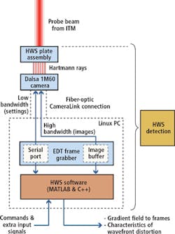
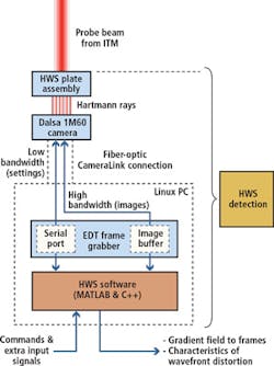
"In the LIGO detector, an auxiliary beam, used to probe the thermal state of the interfometer optics, is imaged onto a Hartmann plate, consisting of a two-dimensional array of apertures, and transmitted onto a 1M60 1024 x 1024 CCD camera from Teledyne DALSA (Waterloo, ON, Canada;www.teledynedalsa.com). This is used to record the thermal state of the optics."
Here, the camera is used to record the interference pattern. With a maximum frame rate of 60fps, 11-bit pixels (corresponding to a 66dB dynamic range), images are then captured using a PCIe4 DVa CLink frame grabber from Engineering Design Team (EDT; Beaverton, OR, USA;www.edt.com), which is housed in a Linux PC running the Ubuntu 10.10 OS.5 operating system. This frame grabber is interfaced to the 1M60 camera using EDT's RCX CLink optical fiber interface allowing the camera to be positioned 100m from the host computer and image data rates of 120MBytes/s to be achieved.
To control the camera and the frame grabber, compiled MATLAB (MathWorks; Natick, MA ,USA;www.mathworks.com) and C++ code is used to extract individual frames from the camera. Using this software, frames are summed pixel by pixel to increase the photo electron number for each pixel and reduce the effect of shot noise. The position of the centroid of each spot in the summed frame is then calculated. When subjected to a gravitational wave, the distance of the two arms of the interferometer will change producing a measurable interference pattern, a technique that scientists at LIGO used to confirm Albert Einstein's 100 year-old prediction. Further information about the design of the system can be found at: bit.ly/1UYHKUN.

