Computer-aided design systems team with machine vision for quality assurance of metal parts
To guarantee that their products are fabricated of the highest quality, machine builders and other industries demand that the metal parts they use are manufactured to the highest standard and inspected before shipping. Companies that supply these metal parts often use laser cutting tools that, guided by computer numerical control, guide a laser beam to cut these parts from large sheets of flat metal. Once such parts are cut, they are then polished and must be inspected to meet the specifications dictated by the computer-aided design (CAD) file supplied by the manufacturer's customer.
Sturm-Gruppe (Salching, Germany; www.sturm-gruppe.com) has a history of manufacturing such laser-machined parts dating back to 1993 when it was founded as Sturm Blechverarbeitung. Now, teaming with Stemmer Imaging (Puchheim, Germany; www.stemmer-imaging.com), the company has recently developed a machine vision system that is used to inspect these metal parts after they are cut and polished.
"After CAD files are received from our customers," says Dr. Wolfgang Ullrich, Branch Manager of Sturm Vision Technologies, a division of Sturm-Gruppe, "they are stored in a database and used to direct a laser-guided cutting machine to cut the part. After the parts are cut, they then are polished and laser engraved with a numerical code."
Reading code
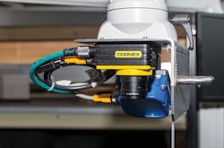
To check that these parts meet the specifications of the CAD file, parts are first manually loaded onto a conveyor that runs at approximately 20m/minute. To check the type of each part, the alphanumeric code on each part must first be checked and compared with the part number in the database. To accomplish this, the part is first illuminated with a SCC75 brick light from Smart Vision Lights (Muskegon, MI; www.smartvisionlights.com) and images of the part captured using an In-Sight Series 7402 smart camera from Cognex (Natick, MA, USA; www.cognex.com) that is mounted on an arm above the conveyor belt (Figure 1).
Running PatMax and OCV software, the alphanumeric code on the part is first read and the result transferred over the cameras Ethernet interface to a host PC where it is compared with that of alphanumeric data from known parts. Should a part be unable to be read, the operator is flagged to remove the part from the conveyor.
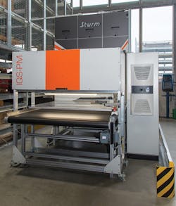
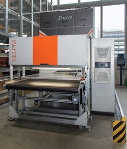
After each part passes inspection, it must be measured to ensure that its characteristics meet that of the CAD data stored in the systems database. To do so, parts moving along the 170cm broad conveyor are first transferred into an imaging station. Here, two white LED custom panel lights manufactured by Sturm-Gruppe mounted at 45° angles in an off-axis configuration are used to illuminate the parts (Figure 2).
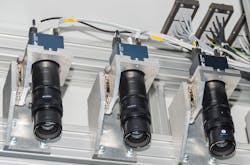
This off-axis configuration is used to highlight the edges of each part as it passes under the imaging station. As the parts are illuminated, they are imaged by eight Spyder3 4k GigE line-scan cameras from Teledyne DALSA (Waterloo, ON, Canada; www.teledynedalsa.com) fitted with 150mm lenses from Schneider Kreuznach (Bad Kreuznach, Germany; www.schneiderkreuznach.com). These cameras were mounted approximately 1.5-2m above the conveyor belt to ensure that an optical resolution of 110 μm/pixel resolution was achieved.
Near telecentricity
"While fewer line-scan cameras with telecentric lenses could have been used in this application," says Georg Schelle, Senior Key Account Manager at Stemmer Imaging, "multiple cameras and conventional lenses were used to reduce the cost of the system." To accomplish this pseudo-telecentric image capture, the full 4k image from each of the eight cameras was not used - rather only a 2k sample from the center of each camera was captured.
Of course, custom calibration of multiple line-scan cameras is not an easy task, as noted by Douglas Wilson in his article "Custom calibration supports linescan system design," (Vision Systems Design, December 2011; http://bit.ly/1HB2JDc). To calibrate the system developed by Sturm-Gruppe, a calibration target is placed on conveyor belt and the operator then enters specific target values.
Once calibrated, image data from the eight cameras used in the system is then transferred over each camere's GigE interface to a 16-port GigE switch and the combined data then transferred to the systems host PC. Images captured by the camera must then be analyzed and compared with the known good data in the systems CAD database.
Matching CAD data
This, perhaps, is one of the most unique parts of the system. Using software developed by Sturm-Gruppe, images are first thresholded to remove the image of the background image conveyor. Using shape finding and blob analysis tools, the contours and edges of objects of the metallic parts are then computed and stored in a database.
However, this data cannot be compared directly with the information stored in the CAD model. Rather, Sturm-Gruppe has developed software that translates the information found in a standard CAD file in formats such as .dxf or geo format into a TIFF image file. Data from this TIFF file can then be read by the image processing software and compared with the image data captured from the metallic part captured by the line-scan cameras.
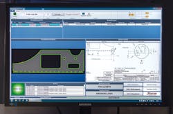
After this comparison, the known deviations from the CAD model are then displayed on the operator's monitor as green (complete match), yellow (partially good) or red (wrong) see Figure 3. Parts that are not deemed sufficient are then removed by an operator after it emerges from the vision station.
When a part is good, the system then generates a label indicating the part type, date of manufacture and other information that is manually affixed to the part. At present, Sturm-Gruppe is using its vision for in-house use but plans to market this to other interested parties.
Acknowledgement
The author would like to thank Georg Schelle, Senior Key Account Manager at Stemmer Imaging with his help in the preparation of this article.
Companies mentioned
Cognex
Natick, MA, USA
www.cognex.com
Stemmer Imaging
Puchheim, Germany
www.stemmer-imaging.com
SturmGruppe
Salching, Germany
www.sturm-gruppe.com
Smart Vision Lights
Muskegon, MI, USA
www.smartvisionlights.com
Schneider Kreuznach
Bad Kreuznach, Germany
www.schneiderkreuznach.com
Teledyne DALSA
Waterloo, ON, Canada
www.teledynedalsa.com
About the Author

Andy Wilson
Founding Editor
Founding editor of Vision Systems Design. Industry authority and author of thousands of technical articles on image processing, machine vision, and computer science.
B.Sc., Warwick University
Tel: 603-891-9115
Fax: 603-891-9297
