Automotive inspection: Multi-camera vision system verifies buckle assembly
When it comes to manufacturing automotive safety components, quality rigors are quite extreme and there is little room for error. That's why leading automotive manufacturers and their suppliers rely on machine vision systems to ensure that only the highest quality components and subassemblies make it into the vehicles that are sold to consumers.
Safety-belt buckles are a case in point. Each buckle has numerous components whose presence and position enable the buckle to latch securely and function as intended. Every component must be intact and in place. Any error, such as a misplaced spring or missing tab on a clip, could potentially lead to the buckle being unable to latch or, in rare instances, making a passenger think the buckle is latched when it isn't.
Many of these inspection applications require the use of multi-camera vision systems that allow the viewing of complex assemblies such as this from different angles. This was the task faced by engineers at Vista Solutions Inc. (Windsor, ON, Canada;www.vistasolutions.com) when developing a buckle assembly inspection system for a high-speed robotic assembly line at Tokai Rika Quality Safety Systems (TRQSS; Tecumseh, ON, Canada; www.tramgroup.com).
"Because there are so many parts in this assembly, we have to perform 15 inspections in 200 milliseconds to make sure each buckle is functional," explains Peter Denzinger, Technical Director, Vista Solutions Inc. "The challenge is that blinking your eye takes 300-400 milliseconds, and in this system, due to the orientation of the cameras with respect to each other, we must strobe the lights individually to avoid crosstalk and acquire images at 10 millisecond intervals."
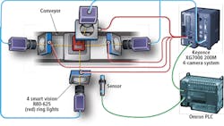
This need for camera sequencing was one reason that engineers specified an XG7000 200M four-camera vision system from Keyence (Osaka, Japan;www.keyence.com) for this application. Denzinger noted that other reasons included the customer preference for non-pc based vision systems and the reasonable cost at which it provided a four-camera vision system.
Denzinger and his colleagues at Vista Solutions used four red R80-625 ring lights from Smart Vision Lights (SVL; Muskegon, MI, USA;www.smartvisionlights.com) to illuminate each buckle assembly for inspection. According to Denzinger, "these high-intensity, high-quality, industrial lights require only power and a trigger signal to function. They are triggered directly by the Keyence multi-camera vision system that includes the dedicated vision hardware required for easily triggering the lights and the cameras within a few milliseconds of one another."
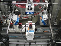
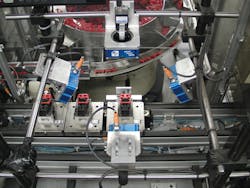
During operation, buckle assemblies traveling on small pallets along an assembly conveyor move into the inspection station. Upon arrival, the pallet carrying the buckle assembly hits a hard stop. It is lifted and then clamped into position by a pneumatic cylinder. A sensor on the locking cylinder signals a PLC from Omron Electronics LLC (Schaumburg, IL, USA;www.info.omron.com) that the pallet is locked in position for and ready for inspection. The PLC then signals the Keyence vision system to trigger the lights and camera acquisition.
The Keyence system then triggers individual light, with 10-milliseconds of separation between each, and the cameras capture the required images 10 milliseconds apart. "We needed to sequence the acquisition to make sure that the lights weren't interfering with the other acquisitions, but it had to be very quick because we are inspecting at a rate of approximately 45 parts per minute," notes Denzinger.
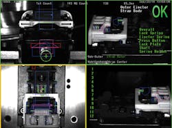
Each acquisition takes about a half a millisecond. After the four images are acquired, processing begins. When analyzing the image from the first camera, the vision system verifies the buckle type (strap vs. web), and makes sure that the ejector spring, lock plate and lock spring are present. This image is also used by the vision system to check for a missing or misassembled press button, and to ensure that the spring holder, cam, shaft and lock spring are present.
Images from the second camera are used to verify that the center and outer ejectors are present, and that the ejector spring is present and not buckled or misassembled. This image is also used to verify that the lock plate is present, and is not misassembled. Images from the third and fourth cameras are used to verify that the lock spring is properly installed and to check the lock spring for end defects.
Buckles that pass inspection move on to secondary processing where the buckles are staked onto straps. Failing buckle assemblies end up being sorted into a defect containment bin, and all failing images are archived and fail data is also logged to a database.


