Industry Solutions: Multiple cameras inspect small parts at high speed
Inspecting multiple aspects of small parts is accomplished using multiple cameras integrated into a single system.
Mario Regazzoni
Although small parts such as washers, screws and grommets can be inspected by human operators, the task is tedious, time consuming and repetitive. Furthermore, such inspections are subject to human error and, since such tasks cannot be accomplished at high speed, machine vision systems are deployed to perform such tasks.
As well as performing such tasks faster, such machines can image multiple views of each part ensuring that every aspect of the part has been manufactured correctly. To accomplish this, such vision-based machines must employ multiple imaging stages, often with different lighting, camera systems and lenses to perform this task.
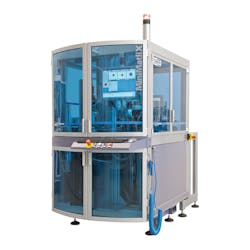
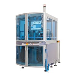
Understanding this, UTPVision has developed a rotary table-based inspection system to perform this task (Figure 1). In operation, parts are loaded from a rotary table where the parts are inspected at multiple imaging stations for top defects, bottom defects and inside and interior defects. The system, previewed at last year's VISION 2016 trade show and conference in Stuttgart, Germany, uses multiple vision inspection stations to inspect all aspects of small components such as washers, screws and grommets. At the show, the system was shown inspecting rubber grommets at 100 parts per minute.
Dimensions and surfaces
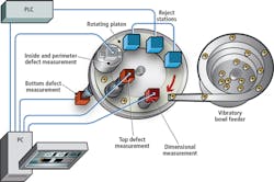
After parts are fed by a vibratory bowl feeder (VBF) onto the system's rotary plate, they are indexed to be imaged by the vision systems (Figure 2). As each part rotates, a laser displacement sensor from Keyence (Osaka, Japan;www.keyence.com) is used to measure the height of the part and, after a delay, trigger the camera at the first inspection station. At this station, the dimensions of the part are inspected.
To accomplish this, a Manta G-504, GigE camera from Allied Vision (Stadtroda, Germany;www.alliedvision.com) with a 2/3in 2452 × 2056 CCD sensor fitted with a telecentric lens from Opto Engineering (Mantova, Italy; www.opto-engineering.com) is mounted above the rotary plate. Color images from this camera are then transferred to the system's host PC over the camera's GigE interface.
As the part is indexed to the next imaging station, images of the top surface of the part are captured. To do so, a second Manta G-504, GigE camera is fitted with a 35mm lens from Computar, Cary, NC, USA; http://computar.com) and placed above the rotating plate. To image the curved, often specular surfaces accurately, the angled, textured, or topographic features are illuminated by a dome light that is placed in close proximity to the sample being imaged.
Different colors
Because the different parts being inspected may reflect and/or absorb wavelengths of light differentially, the custom dome light used in the system incorporates both red and green LEDs. As the part enters the inspection station, the part is then diffusely illuminated by both red and green light.
In this way, by illuminating the part with red light, color surface features of a red color will be reflected and opposing surface feature colors such as green will be darkened. Similarly, illuminating the part with green light, color surface features of a green color will be reflected and opposing surface feature colors such as red will be darkened. After the parts are illuminated, at these two different wavelengths, the two images are combined and transferred to the system's host PC over the camera's GigE interface.
While the camera/dome illumination system is used to capture images of the top surface of the parts, another imaging station (not shown) configured in the same way is mounted under the platen as it rotates. In this way, images of the bottom surface features of the parts can be captured and again transferred to the host computer.
Inside parts
As well as capturing the height information and top and bottom surface features of the parts, it is often necessary to capture the outside and inside surface features of the part. In the case of rubber grommets, for example, the parting line on the outside circumference of the part must be analyzed as well as any defects that may occur on the inside circumference of the parts.
While specialized pericentric and catadioptric lenses can be used to reduce the number of cameras and lenses to perform this task, in some cases, the resolution attainable is insufficient to resolve the detail required. In such cases, multiple camera/lens solutions are needed.
To accomplish this task in the rotary table-based inspection system, UTPVision has developed a specialized imaging system that uses no less than 12 cameras to perform the task. As parts are rotated under the imaging system, six custom cameras based on 1600 x 1200 CCD imagers from Sony (Tokyo, Japan;www.sony.com) mounted horizontally 60o apart are triggered to image the outside circumference of the part. At the same time, six cameras, also based on 1600 x 1200 CCD imagers from Sony are mounted vertically at 45o angles to image the inside diameter. Images from all 12 cameras are then transferred over a GigE interface to the system's host computer.
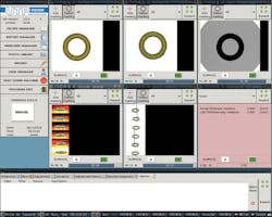
As images are captured by the system, they are displayed on a graphical user interface on a flat panel monitor (Figure 3). The interface, that was written using GTK+, a C-based toolkit for creating GUIs from The GTK+ Project (www.gtk.org), allows the user to visualize (clockwise from top to bottom), the dimension of the part, it's surface features, the outside rim of the part and its inside features. Thus, the operator can visualize the performance of the various imaging stations as the machine processes the images.
Supervised learning
Rather than use standard image processing algorithms such as feature analysis to detect specific features, defects of color of each part, the system uses Retina, a C/C++ library-based on artificial intelligence developed by Squeezebrains. Unlike unsupervised or semi-supervised learning algorithms, Retina analyzes images with a proprietary algorithm, requiring the operator to train the system using a set of images. Because of this, configuration parameters are needed since the parameters are the images used for training. In such supervised learning systems, the input variables (in this case images) and output variable (pass or fail) is used by the algorithm to learn a mapping function from the input to the output.
In the system developed by Squeezebrains - UTP Vision Department, the Retina software is used to process all the images captured from the various machine vision stations of the machine. This eliminates any image pre-processing stages such as image thresholding that are used while maintaining all the information in the captured images.
To train the system, the number of parts that need to be trained depends on the variability of the part being examined. For simple parts, this may be as low as five; for more complex objects, the number of parts may be higher. In a typical scenario, approximately 100 views of an object are first captured. Good and bad parts are then imaged, and with operator input used to train the system by the operator. Once the training is performed, other parts are presented to the system and the system queries the operator as to the condition of the part, reinforcing the supervised machine learning.
After parts are classified, they are indexed around the rotary table. To classify parts according to their defects, a PLC interfaced to the system's host computer triggers blow-off valves from Festo (Esslingen, Germany;www.festo.com) to segment the parts into different bins. By configuring the system in different ways, parts can either be classified as good or bad or alternatively, can be sorted into multiple bins depending on the types of defects detected. In many cases, after sorting, the defective parts can be recycled or reformed.
To date, UTPVision has deployed a number of such systems in Europe, Korea, China and United States of America at a cost of approximately 100k Euros. As a division of UTP, Squeezebrains also offers its Retina software to OEMs developing machine vision systems. Bundled with the GUI, the Retina software is priced at approximately 8k Euros for a single license.
Mario Regazzoni, Managing Director, UTPVision S.r.l and Squeezebrains - UTPVision Department, via Tonale 9, 24061 Albano S. Alessandro (BG), Italy.
Companies mentioned
Allied Vision
Stadtroda, Germany
www.alliedvision.com
Computar
Cary, NC, USA
http://computar.com
Festo
Esslingen, Germany
www.festo.com
Keyence
Osaka, Japan
www.keyence.com
Opto Engineering
Mantova, Italy
www.opto-engineering.com
Sony
Tokyo, Japan
www.sony.com
Squeezebrains
UTP Vision department
Albano S. Alessandro (BG), Italy
www.squeezebrains.com
The GTK+ Project
www.gtk.org
UTPVision S.r.l.
Albano S. Alessandro (BG), Italy
www.utpvision.com


