Image capture: Developments in high-dynamic range imagers
Faced with the challenge of developing high-dynamic range cameras, vendors can choose from a number of different CCD and CMOS devices. In military, automotive and medical applications, for example, such imagers are useful since the larger the dynamic range, the very bright and very dark components of an image can be captured and then processed for further analysis.
Because the dynamic range is the ratio of the largest non-saturating input signal to the smallest detectable input signal, increasing the dynamic range is achieved by either increasing the largest non-saturating input signal or decreasing the smallest detectable input signal.
To date, a number of vendors have tailored their CMOS sensors to increase this dynamic range (see "CMOS imagers look to increase dynamic range"Vision Systems Design, October 2014; http://bit.ly/VSD-14-CMOS). Of course, the two main techniques used to increase this dynamic range: those that modulate the pixel exposure time and those that modulate pixel conversion gain are also being used by vendors of CCDs and CCD-based cameras.
As an example of a CCD-based camera design that use the former approach, the Fusion range of cameras from JAI (San Jose, CA, USA;www.jai.com) encompass a dual CCD architecture in which the shutter speed and/or gain for each channel can be independently controlled so that one channel captures details of brighter areas in the image and one channel darker areas. Fusing these channels together then results in a dynamic range that the company claims is up to 118dB.
On-chip pixel conversion gain methods that employ intensified CCDs (ICCDs), electron bombarded CCDs (EBCCDs) and electron-multiplying CCD (EMCCDs) are also being used by a number of manufacturers including e2v (Chelmsford, UK,www.e2v.com) and Texas Instruments (TI; Dallas, TX, USA; www.ti.com) in their high-dynamic range cameras (see "Disparate detectors enable low-light level cameras," Vision Systems Design, November 2015; http://bit.ly/VSD-15-Low).
One of the most recent of these architectures, the KAE-02150 from ON Semiconductor (Phoenix, AZ, USA;www.onsemi.com) uses EMCCD technology to increase the dynamic range of the 1920 x 1080, 2/3in format, Interline sensor above its normal gain mode of 66dB to an "intra-scene mode" with 86dB of dynamic range. (see "Image sensor technology enables very low light imaging," Vision Systems Design, December 2016; http://bit.ly/VSD-16-Low.)
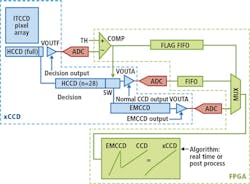
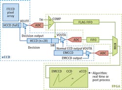
By employing an electron multiplied CCD (EMCCD), this intra-scene switchable gain samples each charge packet on a pixel-by-pixel basis to determine whether the charge is routed through the normal gain output or the EMCCD output based on a user selectable threshold. This enables images to be captured in low-light conditions, when bright objects are within a dark scene.
According to Michael DeLuca, Product Marketing Manager at ON Semiconductor, the device has already been adopted by camera companies such as Bitran (Saitaima, Japan;www.bitran.co.jp) and Imperx (Boca Raton, FL, USA; www.imperx.com) in their latest high-dynamic range cameras.
Designing a camera around such an image sensor, however, is not a trivial task, as Jim DiBella, Director of Camera Development at Imperx points out. As can be seen from the datasheet of the EMCCD (http://bit.ly/VSD-ONSemi), the KAE-02150 uses a quad-output architecture to read pixels from the CCD.
At each stage of the output, a horizontal output register shifts pixels from each quadrant of the device (Figure 1). An output amplifier is then used to sample each pixel before it is digitized to 12-bit values by an FPGA and its value stored in an on-camera FPGA. For the camera to produce a wide dynamic range, pixels with low-light values are shifted through the EMCCD (to increase the gain), digitized and clocked to the FPGA while those with relatively high-brightness values bypass the EMCCD and are again digitized and stored in the FPGA. To select which pixels are to be multiplied by the EMCCD, the original value of the pixel is read, and a threshold is set in the FPGA that is used to clock the pixels through the appropriate channel.
"Both types of pixel data will be digitized to 12-bits," says DiBella. "However, to obtain the 19-bit effective high-dynamic range, the gain applied using the EMCCD must also be applied to the pixels that have not been subject to the EMCCD stage." Then by merging all the pixel data, a high-dynamic range image will be achieved.
Of course, displaying such high-dynamic range images is impossible for even the highest dynamic range monitors to achieve. To allow such images to be viewed, non-linear gamma correction can be applied, translating the 19-bit images to 8-bit images for display. "Such images are generally not used for image analysis-where image processing algorithms are applied to the full dynamic range image-but merely as a tool for the operator to visualize the image," says DiBella.
Imperx has implemented the KAE-02150 in the company's Puma P1940 Camera Link Base camera allowing it to operate as a standard machine vision camera, transferring 1920 x 1080 x 12-bit images at up to 60fps. "However, since the EMCCD runs at 20MHz, using the camera in high-dynamic range mode limits its operation to 30fps," says DiBella. Following the development of its Puma P1940, Imperx will also introduce a high resolution version of EMCCD camera based around ON Semiconductor's KAI-08151, 8.1MPixel EMCCD device, a datasheet of which can be found athttp://bit.ly/VSD-KAE.

