Industry Solutions: Autonomous vehicle driven by vision
Oxford researchers are developing autonomous vehicles that rely solely on vision systems to navigate through their environment.
By Dr. Will Maddern, Senior Researcher, Oxford Robotics Group, University of Oxford, Oxford, UK
Autonomous self-driving vehicles are capable of sensing the environment around them and navigating through it without input from a human being. Early prototypes of such vehicles, however, were expensive due to the cost of the spinning LIDAR scanners that were deployed to measure distances from the vehicles to the environment through which they traveled.
To lower the cost, researchers at the Mobile Robotics Group at the University of Oxford (Oxford, UK;http://mrg.robots.ox.ac.uk) are currently developing a number of self driving vehicles using less expensive technologies.
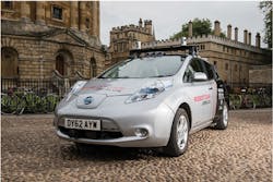
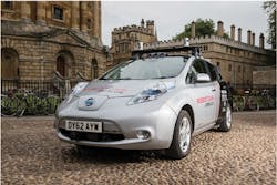
One of the vehicles used to demonstrate the effectiveness of the approach is the Oxford RobotCar platform, an autonomous-capable modified Nissan LEAF onto which a variety of systems such as lasers and cameras are mounted. Data from the systems are transferred to a computer in the trunk of the car which performs all the calculations necessary to plan, control speed and avoid obstacles.
Inside the car is an Apple (Cupertino, CA, USA;www.apple.com) iPad on the dashboard which controls the system. On a familiar route, the iPad offers to take over the driving by flashing up a prompt. Once the driver accepts by tapping the iPad screen, the car's robotic system takes over. The car will stop if there is an obstacle in the road, and the driver can re-take control of the vehicle at any time by tapping the brake pedal.
System hardware
The Nissan LEAF is fitted with two laser scanners mounted on the front bumper of the car. The first of these is a SICK (Waldkirch, Germany;www.sick.com) LMS151 laser scanner mounted in a "push-broom" configuration which scans the environment around the vehicle during forward motion. The second, a SICK LD-MRS, is a forward-facing laser scanner that can detect obstacles in front of the vehicle. A SICK LMS151 laser scanner mounted in a "push-broom" configuration is also fitted to the rear of the vehicle.
The vehicle also sports a number of camera systems. FLIR Integrated Imaging Solutions Inc. (formerly Point Grey; Richmond, BC, Canada;www.ptgrey.com) Bumblebee XB3 trinocular stereo camera with a 24cm baseline, for example, is mounted front and center on the roof above the rear view mirror on the outside of the vehicle, a position that provides the optimum view of objects in front of the car. The trinocular camera is complemented by three other FLIR Grasshopper2 monocular cameras fitted with fisheye lenses strategically placed around the vehicle.
Data from the sensors on the vehicle are logged using an Apple MacPro computer running Ubuntu Linux with two eight-core Intel (Santa Clara, CA, USA;www.intel.com) Xeon E5-2670 processors, 96GByte quad-channel DDR3 memory and a RAID 0 array of eight 512GByte solid state disks, which provided a total memory capacity of 4TBytes.
Acquiring data
The various laser scanners and cameras deployed on the vehicle have been used to acquire data over a number of years for several inter-related research goals.
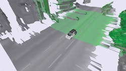
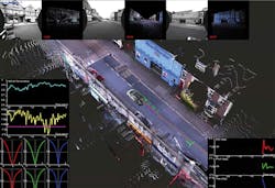
The SICK LMS151 laser scanner, for example, which sports a 270o field of view, can be used to capture multiple 2D scans of the environment as the vehicle moves. From the 2D data collected from the scanner, it is then possible to create a 3D point cloud that represents the environment around the vehicle (Figure 1).
During the developmental stages of the systems for the car, the effectiveness of the front facing SICK LMS151 scanner located 30cm off the ground was compared to that of the rear mounted scanner which sits at a height of 50cm. Having done so, it was discovered that, due to its height advantage, the rear scanner captured a more comprehensive view of the environment and hence it is currently the preferred method of capturing scanned images.
The LD-MRS forward facing laser scanner has been used as a means to detect objects in front of the vehicle. One of the issues with mounting such a sensor on a vehicle, however, is that the sensor can pitch as the vehicle accelerates or decelerates. This potentially could result in erroneous results when the sensor points at the surface of the road.
To circumvent the problem, the LD-MRS detects objects by measuring reflected light from laser beams that the system emits in four stacked planes. From the data, the LD-MRS then calculates the position of the object in the sensor co-ordinate system. Because four beams are used, even if some of the laser light beams are reflected from the road, some will still be pointing forwards. System software can then be deployed to ascertain whether the result of the reflected light actually represents an object.
Camera solution
The holy grail of the autonomous research project at Oxford, however, is to lower the cost of the autonomous system in the car by using cameras as the sole means to acquire data that can be processed to localize the vehicle in its environment and detect any potential hazards.
In one effort to realize such a goal, the Oxford research team has created visual odometery system software that can determine the position and orientation of a vehicle by analyzing the images captured by the Point Grey XB3 trinocular stereo camera.
Although the trinocular camera is supplied with three imagers, in practice only the two outer imagers with a wide 24cm baseline are used to capture the stereo pair of images. For stereo vision, the depth that can be perceived is proportional to the distance between the two cameras, and the error in depth perception is inversely proportional to the same distance. Hence the greater the distance between the two cameras, the greater the measurement accuracy is and the less the error.
In the real world environment, the stereo camera captures a pair of images which are transferred to the Apple MacPro computer which computes stereo correspondences and correct mis-matches.
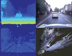
The top right hand image in Figure 2 shows the image captured by the camera on the car while the top left image shows the estimated distance to the objects in the scene. The images have been pseudo-colored, such that the bluer the color of the object, the further away an object is from the vehicle, while the greener it is, the closer it is. From the data, a local 3D representation of the environment can then be built. The bottom right image shows a 3D reconstruction of the scene from a different perspective which was also created from images captured by the stereoscopic camera.
In addition to the Bumblebee XB3 trinocular stereo camera, the experimental Nissan LEAF is also fitted with three Grasshopper2 monocular cameras fitted with fisheye lenses. Two are mounted around the rear of the vehicle behind the rear passenger doors while the third is on the rear of the car facing backwards. The deployment of the three monochrome cameras enables the system to capture an entire 360o visual coverage around the vehicle enabling the system to detect the presence of pedestrians or cyclists.
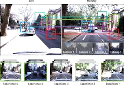
By processing the data from the Grasshopper2 cameras, the vehicle can also be localized within a 3D map (Figure 3). To do so, the Grasshopper2 cameras capture images of the environment as the vehicle moves through it and a previously captured map of the environment is projected into each camera frame. By matching the captured images with the set of points in the map, the location of the vehicle in the map can then be determined.
Experience counts
To realize the potential of the image data captured by the cameras, the research team has developed software to localize the vehicle and detect any potential hazards. One such software suite comprises a set of "experiences" - a set of images that were captured over a period of many months as the vehicle traversed a particular route during different seasons and a variety of weather conditions.
Once the vehicle is in an autonomous self-driving mode, the images captured by the Grasshopper2 cameras are then compared to the stored experiences, and the optimal match is then used to navigate the vehicle through its environment.
During the route, if the system is unable to find an accurate match between the captured images and the experience, the system will add the difference in that data to the experience, lowering the amount of memory needed if an entire new experience were to be added. In use, the system has proved highly effective to the extent that daytime images captured by the cameras can localize the position of the vehicle using an experience captured during the night (Figure 4).
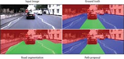
More recent research by the Oxford team has led to the development of deep learning software that can segment proposed drivable paths in images. Using recorded routes from a vehicle, the method generates labeled images containing proposed paths and obstacles without requiring manual annotation. These are then used to train a deep semantic segmentation network. With the trained network, proposed paths and obstacles can be segmented using a vehicle equipped with only a monocular camera without relying on explicit modeling of road or lane markings (Figure 5).
To enable other researchers working on developing autonomous vehicles to perform long-term localization and mapping in real-world, dynamic urban environments, the researchers have also recently released a new dataset.
To create the dataset, the Oxford RobotCar platform traversed a route through central Oxford twice a week on average using the Oxford RobotCar platform between May 2014 and December 2015. This resulted in over 1000km of recorded driving with almost 20 million images collected from six cameras mounted to the vehicle, along with LIDAR, GPS and INS ground truth data. Data was collected in all weather conditions, including heavy rain, night, direct sunlight and snow. The Oxford RobotCar Dataset is now freely available for download at:http://robotcar-dataset.robots.ox.ac.uk
Companies mentioned
Apple
Cupertino, CA, USA
www.apple.com
Intel
Santa Clara, CA, USA
www.intel.com
Mobile Robotics Group
University of Oxford
Oxford, UK
http://mrg.robots.ox.ac.uk
FLIR Integrated Imaging Solutions Inc. (formerly Point Grey)
Richmond, BC, Canada
www.ptgrey.com
SICK
Waldkirch, Germany
www.sick.com
