How to select lighting and optics for Vision Systems
How to select lighting and optics for Vision Systems
Andrew Wilson
Editor at Large
Current machine-vision systems are being used primarily in gauging, inspection, and process-monitoring applications. Although advances in hardware, software, imaging, and camera technologies have reduced application-development times, lighting methods continue to present design challenges to developers of machine-vision systems.
Lighting is still the most critical aspect of a machine-vision application. Choosing the proper lighting scheme can result in increases in accuracy, system reliability, and response time. Developers are making a serious and costly mistake in assuming that inadequate lighting can be compensated for in an algorithm.
Whereas humans use a range of visual cues including color, perspective, shadings, parallax, and individual experiences to gain information from images, machine-vision systems must use predefined routines such as filtering, image subtraction, and histogram-equalization techniques. To ease the burden of software development, vision systems must be provided with images where the areas of interest stand out distinctly against possible inert backgrounds.
Many machine-vision applications have failed for lack of appropriate lighting. Indeed, a lighting method that works in the laboratory often does not translate to the manufacturing floor, where color variations in parts and fluctuating ambient lighting conditions can produce imaging distortions.
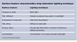
Suppliers continue to improve all their various types of light sources. However, the industry provides as many lighting solutions to enhance a particular object feature as there are applications. To discover which lighting and optics methods are most useful, systems integrators generally experiment with different types of illumination methods, which essentially include structured, backlighting, ringlighting, dark-field illumination, and light diffusion methods (see table on p. 49).
Structured lighting
Structured lighting is generally used in applications that require surface-feature extraction. Illuminating an object with structured light and observing how the object changes the impinging light provides information on the three-dimensional shape of the object. Most commercial laser-line generators use cylindrical optics to expand their beam in one direction. This technique generates a Gaussian line that is bright in its center but fades toward its edges.
According to Lasiris Inc. (St. Laurent, Quebec, Canada), Gaussian lines can cause problems. Because the light intensity of a Gaussian line fades toward its edges, its level eventually falls below the threshold value of the associated detector and becomes invisible to the system. Depending on the detector settings and the light uniformity required, as much as 50% of the available laser power can be lost. And, because light intensity of Gaussian lines is far from uniform, charge-coupled-device sensor calibration becomes difficult.
To overcome this problem, calibrations must be made for the pixels in the bright central area of the sensor, those in the transition area, and the low-intensity end ones. To accomplish proper calibration, Lasiris has developed a patented optical design that produces a non-Gaussian, evenly illuminated line of laser light that eliminates Gaussian-optics-related problems. The company`s latest product, the Micro Focus Laser, produces lines as thin as 8 μm at a precise working distance.
Backlighting defines defects
Diffuse backlighting places the object to be imaged between the sensing lens and the light source. By illuminating the object from the rear, the application background appears uniformly white and the object becomes silhouetted, resulting in a high-contrast image.
"Some defects, such as those in glass plate, however, are impossible to detect using standard backlighting techniques," says Mike Muehlemann, president of Illumination Technologies (East Syracuse, NY). "Such applications present special problems due to the transparent nature of the glass and the diversity and small size of the defects," he adds. Although small opaque defects can be found using conventional backlighting techniques, the most difficult defects to detect are embedded bubbles or stones. They cause a small section of glass to appear thicker (or thinner) than the surrounding glass plate.
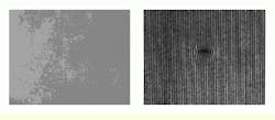
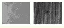
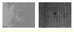
A Zebra backlight from Illumination Technologies is available to handle these problems. With fine, evenly spaced rulings running in the direction of the moving plate, this backlight uses the refractive properties of the glass to create a measurable variation in the pattern (see Fig. 1). The lined pattern is then modified by the otherwise invisible defects. Image subtraction from a reference image of an acceptable product can then determine if there are any changes in the pattern. The resultant image then contains the defect areas only, including both transparent and opaque types.
Removing specular reflection
By controlling the lighting conditions of an application, reflections can be removed from the surfaces of an object at all viewing angles by illuminating the object with polarized light and placing a polarizing filter over the camera lens. Illuminating the object to be imaged with polarized light forms surface specular reflections that are composed of polarized light. This light can be subsequently removed by the filter and camera lens. Total elimination of the specular components is achieved when the filter and polarizer are crossed.
Ringlights provide intense shadow-free on-axis lighting and are highly useful when imaging reflective objects. To further reduce specular reflections from shiny surfaces, ringlights can be used in combination with a polarizer and an analyzer.
At the Engineering Technology Center (ETC) of Analysis and Technology Inc. (Mystic, CT), Doug Wilson and his colleagues have developed DisplayCheck, a PC-based vision system configured to test the integrity of liquid-crystal displays (LCDs), electroluminescent displays, and user-interface firmware (see Vision Systems Design, May 1999, p. 9). Designing the software to handle a variety of display illuminations proved to be a major challenge for ETC engineers. For the fastest and most accurate inspection, the vision system incorporates a fiberoptic ringlight from Fostec (Auburn, NY) to illuminate the display under test (see Fig. 2).
Because external lighting produced glare from the display glass, the vision system could not obtain a high-fidelity image. To overcome this problem, a polarizing filter was positioned in front of the lens of the RS-170 camera. "Because LCDs polarize the reflected light, a polarizing filter is aligned to transmit only that polarity of light," says Wilson, "resulting in a high-fidelity image of the display with no glare."
Dark-field illumination
Many transparent objects are not readily visible when diffuse backlighting is used. In such cases, image contrast can be improved by dark-field illumination. Using this method, the edges of a transparent object appear bright against a dark background. A dark field is achieved by projecting a cone of light from behind the transparent object. If not obstructed by an object, this cone of light diverges from the optical axis and is not imaged. Only the light scattered or reflected by the object is directed into the optical axis and imaged.
"One of the more difficult images to capture is a laser-etched symbol or mark on a shiny surface. Often, the mark and the surface have reflective characteristics, such as a shiny mark on a shiny background," says Allen Burns, sales manager of Northeast Robotics (Weare, NH).
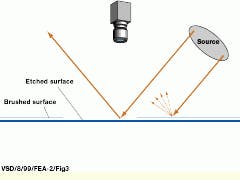
In such applications, dark-field illumination produces a lighting contrast with embossed or engraved surfaces that distinguishes the surfaces of differing textures. Inspecting a laser-etched data-matrix code on a shiny surface, for example, takes advantage of the two surface differences between the mark and the background. "In the area of the mark, a laser etches the "brushed" nickel surface and causes it to appear flat and specular," Burns says. As a result, the mark appears to be located slightly below the surrounding surface and reflects the light at an angle that is different from the background reflection. This brushed surface area surrounding the mark then reflects the light in multiple directions (including toward the camera) and thereby achieves a higher intensity value (see Fig. 3).
This lighting method produces effects similar to those generated by oblique lighting. The difference is that the angle of incidence of the light is placed at a particular angle to the target surface. As the angle of incidence increases, a larger portion of the incident light is allowed to reflect from the flat surface of the test target. This setup reduces the visible contrast of the raised surface target. More information from the flat surface can then be imaged.
Light diffusion
Light diffusion produces an area of uniform illumination that helps to eliminate shadows and minimize specular reflection. Diffusing light is achieved by placing a Mylar screen in front of a light source or by reflecting the light back onto a surface using a white screen, thereby enlarging the area of coverage by the light source. Such diffusion assemblies can use a number of different lighting techniques, such as fiber, fluorescent, or light-emitting-diode illumination.
The Fiber-Lite Diffuse (FLD) optical assemblies from Dolan-Jenner Industries (Lawrence MA), for example, can provide wide-angle, on-axis, or diffuse illumination. The FLD design allows the camera to view an object perpendicularly through the assembly. As a result, reflective objects with uneven surfaces can reflect light to the camera from every point on their surface, thereby eliminating glints and shadows.
When using the diffuse on-axis light (DOAL) assembly from Northeast Robotics, light rays reflect off a beamsplitter directly onto an object at nearly a 90° angle. With this approach, specular surfaces perpendicular to the camera appear illuminated, whereas surfaces at an angle to the camera appear dark. Nonspecular surfaces absorb light and therefore appear dark.
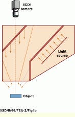
To provide added uniformity for nonplanar surfaces, the Northeast Robotics Square Continuous Diffuse Illuminator (SCDI) reflects light off a beamsplitter and a lower chamber, increasing the solid angle of illumination (see Fig. 4). Because the light source is tilted parallel to the beamsplitter, its uniformity is increased. The SCDI is useful in lighting moderately faceted and undulating specular surfaces.
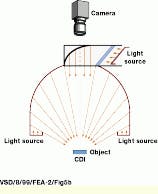
For the most complicated uneven and specular surfaces, the Northeast Robotics Cloudy Day Illuminator (CDI) offers the greatest degree of light coverage. During CDI usage, light rays from two different sources reflect light in a hemispheric pattern (see Fig. 5). The illuminator is aimed at applications involving highly specular surfaces, such as those used for compact disk artwork verification. For these surfaces, reflections of the camera aperture or "seams" in the lighting envelope can cause a vision system to see defects where none exist.
The selection of a lighting and optics method represents the most critical design parameter of a machine-vision system. Consequently, systems integrators must make illumination and lighting choices before specifying the other parts of an industrial machine-vision system. To accomplish this task, they should rely on the experience of illumination and lighting-device suppliers and discuss which lighting and optics methods might prove successful. After the lighting and optics devices are chosen, systems integrators can structure a complete machine-vision system.
FIGURE 1. Detecting defects in glass plate is exceedingly difficult to accomplish using standard backlighting techniques due to the transparent nature of the glass and the small size of the defects.
To solve this problem, a Zebra Backlight from Illumination Technologies generates evenly spaced rulings and, in conjunction with the refractive properties of glass, produces a measurable variation in the pattern.
FIGURE 2. The DisplayCheck LCD inspection system from the Engineering Technology Center uses a fiberoptic ringlight from Fostec to illuminate the liquid-crystal display (LCD) under test. To obtain a high-fidelity image, a polarizing filter is placed in front of the camera lens. Because LCDs polarize the reflected light, the polarizing filter is aligned to transmit only that polarity of light, thereby resulting in an image of the display with no glare.
FIGURE 3. In dark-field illumination, the angle of incidence of the light is placed at an angle to the target surface. As this angle increases, a larger portion of the incident light reflects from the flat surface and reduces the visible contrast of the raised surface target.
FIGURE 4. To provide added uniformity for nonplanar surfaces, the Northeast Robotics Square Continuous Diffuse Illuminator (SCDI) reflects light off a beamsplitter and a lower chamber to increase the solid angle of illumination. Because the light source is tilted parallel to the beamsplitter, light uniformity is increased.
FIGURE 5. For complicated uneven and specular surfaces, the Northeast Robotics Cloudy Day Illuminator (CDI) appears to offer the greatest degree of light coverage. During CDI usage, light rays from two different sources reflect light in a hemispheric pattern. This illumination is useful in applications that involve highly specular surfaces such as for compact disk artwork verification.
Company Information
Dolan-Jenner Industries
Lawrence MA 01843
(978) 681-8000
Fax: (978) 682-2500
Web: www.dolan-jenner.com/
Engineering Technology Center Analysis & Technology
Mystic, CT 06355
(860) 572-9600
Fostec Inc.
Auburn, NY 13021
(315) 255-2791
Fax: (315) 255-2695
Web: www.fostec.com/
Illumination Technologies
East Syracuse, NY 13057
(800) 738-4297
Web: www.illuminationtech.com/
Lasiris Inc.
St-Laurent, Quebec, Canada H4R2K3
(800) 814-9552
Web: www.stkr.com/lasirisprf.htm
Northeast Robotics
Weare, NH 03281
(603) 529-2385
Fax (603) 529-2405
Web: www.nerlite.com/
