DSP array upgrades optical correlation
By R. Winn Hardin,Contributing Editor
The AGM-88 High-Speed Anti-Radiation Missile (HARM) travels 2280 km/h (1416 mph) as it tracks an enemy radar source. In the HARM, guidance is provided by the target, but not all such missile applications are so sophisticated. Smart missiles and bombs made famous by the Persian Gulf War required infantry-support weapons or specially fitted aircraft to latch ("lase") onto a target. The missile then followed reflected coherent light to the target. Improved solutions would not require military personnel to be so close to the target before launching a missile. Such a missile would need to be even "smart," that is, capable of selecting one "key" target or fortification from several and destroy that enemy military asset in the area.
To create self-guiding missiles, the US Ballistic Missile Defense Organization began developing optical processing systems in the 1980s and used laser light and a spatial light modulator (SLM) to compare all pixels in a template against those in an input image. These optical correlators had to keep the optical elements in tight alignment. Unfortunately, missile vibration during flight and alignment errors of just a few microns caused problems.
As part of a two-year project started in 1998, researchers at the University of Sussex in England, who are funded by the UK Optical Systems Integration Programme of the Engineering and Physical Sciences Research Council, have simplified optical-correlator design by replacing the input SLM and accompanying optics with an array of high-speed digital signal processors.
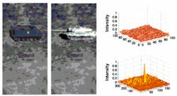
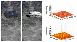
True parallelismTwo-dimensional correlation is a numerically intensive process used in discriminating one target among many. For example, to perform a correlation function on a 512 x 512-pixel input image with a template of 128 x 128 pixels, an optical processing circuit would require approximately 4 billion multiply/adds. Because a number of different templates might be required to define a specific target, the input image must be searched with several templates in a fraction of a second.To speed up the correlation speed, conventional optical correlators can be used. They simultaneously perform a correlation function for all the pixels in the input and template images within the frequency plane. During operation, an input SLM modulates the amplitude of a laser beam with the input image. The reflected light passes through a Fourier lens that produces the image's optical frequency spectrum in its back focal plane in a single step. This light reflects off a second reference SLM that modulates the light's phase and amplitude based on a stored Fourier spectrum of the reference template. The resulting combined signal passes through a second Fourier lens that transforms the signal back into optical space. When a template matches a section of the input image, a correlation peak or a bright spot appears. The x, y location of the correlation peak indicates where the object is in the input image (see Fig. 1).
FIGURE 1. In a hybrid optical/digital correlator simulated target-recognition application, an input image of an armored personnel carrier is the target (left). A second picture of the tank in the field is input as the reference template (right). The result from the carrier/tank comparison is shown in a 3-D surface plot, where no correlation peak is present (top). When the input image is compared with a picture of a personnel carrier, a correlation peak appears in the same x, y position as the target's location in the input image (bottom).
Although the theory behind optical correlation seems straightforward, constructing rugged optical correlators poses several problems. According to University of Sussex project designer Rupert Young, the more optical elements used calls for a more powerful laser and a larger footprint for the correlator. Displacement of optical elements by as much as a pixel (typically between 7 and 40 µm for an SLM) can affect the results of the correlation. However, removing some of the optical elements, including one of the SLMs, reduces this optical path and relaxes the alignment requirements.
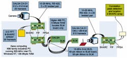
Digital FFTsThe University of Sussex group tested its demonstration system using pictures of tanks and fighter planes as input images (see Fig. 2). A Dalsa GmbH (Munich, Germany) CA-D8 512 x 512-pixel CCD digital camera collects the image of a fighter plane and sends 8-bit/pixel data across an RS-422 cable to a SharcPAC-camera daughter board from Spectrum Signal Processing (SSP; Burnaby, BC, Canada). This board, along with subsequent SSP image-processing boards, is housed in an x86 family Industrial PC from Kane Computing (Chesire, Middlesex, England).The camera interface board feeds the digital image data to a SharcPAC-FPGA10K board. Patrick Mills of Quintek Ltd. (Westbury on Trym, Bristol, England) programmed the on-board Altera (San Jose, CA) 10K-gate field-programmable gate array (FPGA) to match the 10-MHz output from the Dalsa CA-D8 camera to the 40-MHz input of the Analog Devices (Norwood, MA) Sharc 21060 DSP processor. The FPGA configuration was achieved using Altera's MAX+Plus II tool set.
Although slower in operation than many hard-wired fast-Fourier-transform (FFT) chips, software and DSPs were less of a risk to develop than a hard-wired solution. Also, the 2-D FFT for the input image generated a large amount of intermediate data with a broad dynamic range. This type of data required the use of a floating-point method rather than faster fixed-point DSPs for higher accuracy.
At the time, Alex Computer Systems offered its APAC and SPAC lines of accelerator boards based on the Analog Devices Sharc DSPs. Young said that the APAC and SPAC boards were designed for parallel distributed processing as evidenced by the library sets included with the Advanced Parallel Executive (APEX) high-level programming language. APEX was one of the final arguments in the decision to pursue a software approach rather than a hard-wired approach. (Spectrum has since renamed this high-level programming language.)
The Sharc 21060 DSP can share data with up to six other processors without buffer memory or increasing the zero-wait time. Texas Instruments (Dallas, TX) offered the fastest floating-point DSP with its TMS320C67, but OEM boards were not available at the time, Young adds.
Video-rate FFTsFrom the SharcPAC-FPGA10K-gate board, image data are sent through the Sharc card links to a neighboring SharcPAC-DSP2 mezzanine board that resides on the same motherboard ISA card. This passive card, along with two others, is only used as a support structure and as a means to get power to the SharcPAC cards.The SharcPAC-DSP2 mezzanine board contains two Analog Devices Sharc 21060 DSPs. The first pair of Sharc 21060 DSPs feeds one frame at a half-video frame rate to a block of four Sharc 21060 DSPs working in parallel. The second Sharc DSP on the first board sends the second frame at a half video frame rate to a second block of Sharc 21060 DSPs. Each block of four DSPs performs a 2-D FFT on its image. This operation brings the total system throughput back up to video frame rate or 25 frames/s.
Within each block of four DSPs, the input image is shared among the four Sharc DSPs. Each DSP performs a 1-D FFT on a quarter of the rows. The block of DSPs then "turns the corner" in the 2-D FFT, and 1-D FFTs are repeated on each pixel in half the columns of the original input image. The remaining data can be filled in because the 2-D Fourier transform has diametric symmetry. The result is a 2-D FFT where each pixel has a complex value composed of real and imaginary components, each with a 32-bit depth.
After the 2-D FFT has been computed, the data pass through another 40-pin ribbon SharcPAC expansion cable to a SharcPAC-FPGA mezzanine board attached to the industrial PC's custom PCI board. The Sharc 21062 DSP on this board is programmed to convert the complex Fourier data into phasor form.
In the 2-D FFT, each pixel has a complex value, meaning that each pixel has real and imaginary components. A proprietary algorithm running on the Sharc 21062 DSP converts the complex Fourier data into limited, fixed-bit phasor form to speed the combination of the input and template 2-D FFT prior to loading the combined data on the SLM.
In phasor form, the real and imaginary components for a pixel are converted into fixed-bit values that are used to calculate the corresponding magnitude and phase values of the phasor representation of the complex value of the pixel. In this representation, a fast fixed-bit multiply can be carried out with the reference template data. According to Young, as long as the resulting values each have at least three bits of depth, the correlator's ability to function is not significantly affected.
With the input FFT spectrum in phasor form, the FPGA multiplies each spectral component with the stored phasor of individual template image spectra. To multiply complex values in phasor form, the magnitude's fixed-bit values are multiplied and the fixed-bit phase values are added. By limiting the phase and magnitude values to a fixed-bit rather than floating point and adding a look-up table for the conversion from phasor back to real and imaginary component form, the FPGA can process data equal to 1000 frames per second at a 512 x 512-pixel resolution.
When the resulting spectrum is displayed on the 8-bit SLM, the resulting product phasors must be displayed as real and imaginary components. Therefore, each component is allocated its own pixel, resulting in pixel pairs being used to represent the complex value spectral components on the SLM. Young says that while this does reduce the SLM's
resolution, it improves the correlator's ability to find matches between the templates and the input image over previous approaches, which discard amplitude information altogether and only display the phase of the spectrum on the SLM.
Target recognitionAfter the input FFT and template FFT are combined, the resulting FFT spectrum signal passes across a 40-pin ribbon cable to the PCI card that controls the Boulder Nonlinear Systems (BNS; Lafayette, CO) 8-bit, 128 x 128-pixel, ferroelectric liquid-crystal SLM. The University of Sussex group put the SLM in a separate Viglen House (Alperton, Middlesex, UK) PC host so that they could interrupt the SLM at any time through the BNS SLM control software during testing. The DSP boards, however, are installed in the x86 industrial PC to accommodate their size and provide better cooling (see Fig. 3).Light from a Power Technology (Little Rock, AR) 670-nm, 7.5-mW diode laser is expanded into a Gaussian profile of the same size as that of the SLM. A mirror and a beamsplitter direct the beam to the SLM, which modulates the magnitude and phase of the laser light. The light then passes through a Fourier lens arrangement, designed by Gongde Li of the University of Sussex group, using the Focus Software (Tucson, AZ) Zemax lens design package and manufactured by Achro Optics Ltd. (Saint Leonards on Sea, East Sussex, England). The Fourier lens converts the spectrum from the frequency plane to the optical plane, and the result is conveyed by a fiberoptic bundle to a high-speed Dalsa CA-D1 128 x 128 x 8-bit digital camera that operates at 915 frames/s.
If no match exists, the camera sees nothing. If the template matches some portion of the input image, the camera captures a bright correlation spot showing where the object is located within the overall 512 x 512-pixel input frame. Output from the 128 x 128-pixel camera also can be viewed on the Industrial PC 21-in. Hitachi (Maidenhead, Berks, England) CM802 ET monitor through a Matrox Imaging (Dorval, QC, Canada) Millenium II video card, with command control provided by the "display" library in the APEX DSP software. Because of the demonstration nature of the system, the University of Sussex group has yet to integrate the correlator into a system that would convert a correlation point to guidance coordinates.
During the three years since the University of Sussex group began the hybrid correlator projector, DSP chip sets have more than doubled in speed. Young expects that DSP technology will continue to improve with the provision of higher clock rates, larger amounts of on-chip memory, increased data-transfer bandwidths, and lower costs, making it easier to accomplish the input FFT.
SLM technology also continues to improve, he adds, not only in binary ferroelectric devices developed primarily for display applications, but also among analog high-frame-rate SLMs designed explicitly for optical processing needs.
ACKNOWLEDGMENT The author thanks Chris Chatwin, project leader; Rupert Young, overall system design; Frederic Claret-Tournier, David Budgett, Shiping Huang, and Triantafillos Koukoulas, digital signal processing and software engineering; Phil Birch, electro-optics of spatial light modulator; and Gongde Li, optical and optomechanical design at the University of Sussex for their assistance.Company InformationAlteraSan Jose, CAWeb: www.altera.comAnalog Devices
Norwood, MA 02062
Web: www.analog.com
Boulder Nonlinear Systems
Lafayette, CO 80026
Web: www.bnonlinear.com
Focus Software Inc.
Tucson, AZ 85731
Web: www.focus-software.com
Hitachi Europe Ltd.
Maidenhead, Berks SL6 8YA,
England
Web: www.hitachi-eu.com
Hitachi Koki Imaging Solutions
Simi Valley, CA 93063
Web: www.hitachi-hkis.com
Kane Computing
Northwich, Cheshire CW9 5HB, England
Web: www.kanecomputing.com
Matrox Electronic Systems
Dorval, Quebec H9P 2T4, Canada
Web: www.matrox.com/imaging
Power Technology Inc.
Little Rock, AR 72219
Web: www.powertechnology.com
Quintek Ltd.
Westbury on Trym, Bristol BS9 3BH, England
Web: www.apgate.com
Sharp Electronics UK Ltd.
Manchester, M4D SBE, England
Web: www.sharp.co.uk
Spectrum Signal Processing
Burnaby, BC V5A 4X1, Canada
Web: www.spectrumsignal.com
Viglen House
Alperton, Middlesex, HA0 1DX, England
Web: www.viglen.co.uk


