Smart vehicles
Smart vehicles use a vision system to detect other vehicles, respond to traffic signals, and avoid pedestrians and obstacles.
By C. G. Masi,Contributing Editor
Actor Arnold Schwarzenegger searches for his clone in the motion picture The Sixth Day and is driven to an airport by an intelligent car. Detecting close traffic, pedestrians, and surrounding highways, the car appears to drive itself as the driver sits behind a steering wheel.
Such a smart-vehicle system appears more plausible to the general public than it does to systems integrators who know the complexities involved in a vision system imaging a target-rich environment. Yet, researchers at DaimlerChrysler Research (Ulm, Germany) have built a smart-vehicle-theory demonstrator called the Urban Traffic Assistant (UTA) that uses brute-force calculations performed off-line from images stored on video tape.
As yet, the UTA cannot make complex decisions. However, the DaimlerChrysler research team has demonstrated that by using a multitude of algorithms it can maintain separation from the vehicle ahead, see and respond to traffic signals, and avoid pedestrians and obstacles while moving through urban traffic situations at normal driving speeds under the supervision of a human driver.
Hardware architecture
A pair of video cameras from JAI AS (Copenhagen, Denmark) serve as the UTA's eyes. Arranged in a stereo configuration, the cameras are mounted on a horizontal bar near the rear-view mirror. The bar separates the two cameras by approximately 30 cm and maintains their orientation. The horizontal scan lines of both cameras must be tightly aligned and strictly parallel to the line joining their optical axes. Furthermore, the cameras' optical axes must be coplanar, as well. These specifications are needed because the vision system must infer a correspondence between the scan lines of one camera and those of the other. These video cameras provide progressive-scan images with 720 x 576-pixel resolution.
The UTA uses an Imaging Technology Inc. (now Coreco Imaging; St Laurent, Que., Canada) IMPCI frame grabber and a commercial monitor with 1024 x 786-pixel resolution. Its central processing unit comprises several Ethernet-interconnected general-purpose PCs with dual-Pentium 600-MHz processors, MMX-based technology from Intel Corp. (Santa Clara, CA) for image processing, and one Motorola (Tempe, AZ) Lynx/604e PowerPC for controlling the vehicle's sensors and actuators (see Fig. 1).
The vehicle's video sensors and display are connected directly to the PCs, rather than via the system's controller-area network (CAN) data bus—a serial data-communications bus especially suited for networking "intelligent" devices as well as sensors and actuators in real-time applications. The CAN bus, originally developed by Robert Bosch GmbH (Reutlingen, Germany; www.can.bosch.com) for use in cars, has now found use in other industrial automation and control applications.*
The CAN bus cannot support the high transfer rates associated with full-resolution video at high frame rates. However, it does carry the vehicle sensor data (longitudinal speed, longitudinal and lateral acceleration, yaw and pitch rate, and steering wheel angle) and actuator data (throttle, brake, and steering actuators).
Software architecture
Driver-assistance imaging systems are challenging not only from the coding aspect, but also from the software-architecture point of view. The architectures of most driver-assistance systems are tailored to a specific application, such as lane-keeping on highways. Here, the functionality is achieved by a few computer-vision and vehicle-control modules that are hard-wired together. Although this kind of architecture is suitable for many imaging applications, the growing complexity of driver-assistance systems reinforces the development of software architecture that can deal with the different abstraction levels of action-perception control, sensor fusion, integration and cooperation of various software modules, economical use of resources, scalability, and distributed computing.
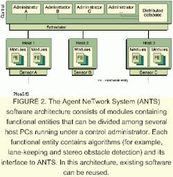
A multiagent-system approach is used by the UTA developers to meet these requirements (see Fig. 2). Called the Agent NeTwork System (ANTS), this approach makes an explicit distinction between the host functional-entry (FE) modules and their interconnections to perform a specific application.1
FIGURE 1. The Urban Traffic Assistant "brain" consists of a set of MMX-based PC computers interconnected via Ethernet. They communicate with sensors and actuators on the vehicle itself via a slower system CAN bus, which allows the system to guide the vehicle autonomously.
The flexible ANTS software architecture allows the development of various applications without modifying the modules. Moreover, this system also allows run-time connection changes, which enables economical use of computational resources and adaptation to the situation. For example, lane-keeping on highways and dynamic task switching to intelligent stop-and-go applications can be accomplished today.
System connections are established by so-called administrators. An administrator controls a set of modules. It chooses which of them has to be executed next and hands them over to the scheduler. Modules are the computational components of ANTS. They can be distributed on several hosts and are handled uniformly by the system via a distributed database and communications interface; they are implemented using a parallel virtual machine package.
FIGURE 2. The Agent NeTwork System (ANTS) software architecture consists of modules containing functional entities that can be divided among several host PCs running under a control administrator. Each functional entity contains algorithms (for example, lane-keeping and stereo obstacle detection) and its interface to ANTS. In this architecture, existing software can be reused.
A module consists of several FEs. Each FE contains algorithms (for example, lane-keeping and stereo obstacle detection) and their interfaces to ANTS: existing software can be reused; the developer of an algorithm doesn't have to take into consideration the details about other ANTS components, such as administrators; and the developer of an administrator doesn't have to know the exact details of the modules.
Connecting a group of modules forms an application. One version of pedestrian recognition, for example, combines several classifiers and a stereo obstacle detection algorithm. The stereo algorithm delivers candidate objects, which are used as input for the pedestrian classifiers. An administrator merges these asynchronous results from the different classifiers, which, finally, allows the classified objects to be tracked by a stereo object tracker.
Pattern-matching
None of the system software works, however, without a reliable algorithm for singling out important objects in the scene and identifying them. To be useful in autonomous vehicle development, this algorithm must run in real time.2
FIGURE 3. The probability of a perfect match between any template and any object in a real scene is extremely small. In practice, pattern-matching algorithms require only that the score be less than an arbitrarily assigned value. Even though the scale and orientation of the template are perfect relative to the image, an upward or downward displacement by one pixel can change the score from a perfect match to all pixels mismatched.
Fortunately, people are adept at solving object-identification problems. For example, they can immediately interpret any pattern consisting of two small, circular features approximately equally spaced above a horizontally elongated feature as a human face. This illusion is strong even when the basic pattern is scaled to any size or turned to any orientation.
The problem with pattern-matching in real-world vision applications is that objects present a range of appearances due to different lighting conditions, viewing angles, and shape and texture properties. In the case of reading a road sign, the image appearance changes constantly as the viewing angle changes. A pedestrian presents a more difficult challenge because the object to be detected is not rigid. That is, the pedestrian's outline changes as arms and legs move. Both targets present a variety of possible shapes, as well.
DaimlerChrysler researchers have developed object-recognition algorithms that use a variety of vision cues, such as depth, motion, texture, and shape, to increase robustness. For example, consider an approach based on an important shape cue. Simple shape-based template-matching involves extracting "features" from images that consist largely of edges from the acquired scene and comparing those features to a template on a pixel-by-pixel basis. Feature extraction consists of using edge detection to classify image pixels as either feature or nonfeature pixels. Pixels in the template are similarly classed as feature or nonfeature pixels.
FIGURE 4. A distance transform (DT) associates a number representing the distance from that pixel to the nearest feature pixel. The DT associates a number with each pixel in the image feature array, which measures the distance between that pixel and the nearest image-feature pixel. A DT value of zero equates to a feature pixel.
The pattern-matching algorithm uses a series of scaling, rotation, and translation transformations in an attempt to identically overlay the template feature pixels onto the image feature pixels. If enough of these feature pixels match, the object in the image is assumed to be identified by the template.
Generally, algorithms take the number of mismatches as a measure of the fit. That is, if all feature pixels in the template match all the feature pixels in the image, the score is zero and the match is considered perfect.
The probability of a perfect match between any template and any object in a real scene is, of course, extremely small. In practice, pattern-matching algorithms require only that the score (s) be less than an arbitrarily assigned value (e). Unfortunately, s is not usable as a goodness-of-fit variable for optimization algorithms because its behavior is both highly nonlinear and unpredictable. Even though the scale and orientation of the template are perfect relative to the image, an upward or downward displacement by one pixel changes the score from a perfect match (s = 0) to all pixels mismatched (see Fig. 3).
FIGURE 5. The chamfer shape-matching process starts with a scene image and a template. An edge detection algorithm extracts the feature pixels from the scene image to form a feature image. The distance transform then calculates the distance from each non-feature pixel to the nearest feature pixel in a distance image. Feature pixels are represented with zeros. If the correlation consists of applying a random set of scalings, rotations and translations to the template, then compute the goodness-of-fit score. If the score is driven below some predetermined value, the template is said to match the object in the scene.
Dariu Gavrila, a research scientist in the Image Understanding Systems Group of DaimlerChrysler Research, has solved this problem using what he calls the chamfer system for matching templates to patterns. The chamfer system is an adaptation of an older idea called the distance transform (DT)3 (see Fig. 4).
The DT associates a number with each pixel in the image feature array, which measures the distance between that pixel and the nearest image-feature pixel. Obviously, the number associated with feature pixels is zero. The DT image, therefore, "fuzzes out" the sharp demarcation between feature and nonfeature pixels (see Fig. 5). The pattern-matching algorithm applies the transformed template to the DT image rather than to the feature image. The score then becomes the sum of all DT values associated with the template features
null
where D (T, I) is the quality-of-match score, I is the image being matched, T is the template-feature matrix, d(i) is the value in the ith pixel of the distance-transformed image, and di,t is the Kronecker delta function (equals 1 if i = t and equals 0 otherwise).
The advantage of DT matching is that D (T, I) is reasonably well behaved for small misalignments and mis-scalings of the template. Users can be confident that for any two slightly different templates, the one that most closely matches the object in the original image will have the lower score. DT matching can, therefore, be used as a "goodness-of-fit" measure in an optimization routine searching for the best match.
Simple DT matching, however, falls short when users try to compare templates of different complexities and sizes. Larger and more-complex templates tend to have more feature pixels. Therefore, they tend to have a higher score (indicating to the optimization routine that the match is poorer) than simpler or smaller templates.
The chamfer system solves this problem by computing the average distance to the nearest image feature, called the chamfer distance
null
where |T| is the number of feature pixels in the template. The chamfer system is used to find the set of scalings, rotations, and translations that provides the best match between a template and an object in the scene.
In practice, templates are arranged in a hierarchy to improve the efficiency of searches. For example, near the top of the hierarchy, templates are separated into objects that extend up into the air (which could be road signs or traffic signals), objects lying flat on the pavement (which could be road markings), and objects sticking up from the pavement (which could be pedestrians, other vehicles, or obstructions). The next level under objects-that-could-be-signs might distinguish between square signs, round signs, and triangular signs. By navigating downward through the hierarchy, users expect to see lower D values, indicating better and better matches.
This template hierarchy drastically reduces (on average) the number of templates that need to be tried against the feature matrix. Since trial matching is the most computation intensive part of the whole process, reducing the number of trials needed to identify an object vastly speeds up the system's response time.
REFERENCES
- S. Görzig and U. Franke, Proc. IEEE International Conference on Intelligent Vehicles, Stuttgart, Germany, 545 (1998).
- U. Franke et al., Proc. IEEE Intelligent Systems 13(6), 40 (1998).
- D. M. Gavrila and V. Philomin, "Real-Time Object Detection for Smart Vehicles," Proc. IEEE International Conference on Computer Vision, Greece (1999).
- Fundamentals of Optics—An Introduction for BeginnersBy Reinhard Jenny, Volpi AG
- Fundamentals of Fiberoptics (for Illumination)By Reinhard Jenny, Volpi AG
- Benefits of Xenon Technology for Machine Vision IlluminationBy D. Jacobsen and P. Katzman, PerkinElmer Optoelectronics
- Theory & Application of Digital Image ProcessingBy A. Erhardt-Ferron, University of Applied Sciences, Offenburg
COMPANY INFORMATION
Coreco Imaging
St Laurent, Quebec
Canada H4T 1V8
Web: www.imaging.com
DaimlerChrysler AG
Stuttgart, Germany
Web: www.daimlerchrysler.com
Intel Corp.
Santa Clara, CA 95052
Web: www.intel.com
JAI AS
Copenhagen, Denmark
Web: www.jai.com
Motorola
Tempe, AZ 85282
Web: www.motorola.com


