Nonimaging sensors direct vision systems
Acting as system gatekeepers, nonimaging sensors trigger cameras and track part movement.
By R. Winn Hardin, Contributing Editor
Photoelectric sensors and emitters, optical encoders, and proximity switches are the most common types of nonimaging sensors that help vision systems avoid false-negative results by keeping the vision system on track and acting as gatekeepers. These sensors help the system know when to acquire an image and communicate meaningful information to mechanical systems and PLCs further down the line or record data more specific than batch or shift results.
Explains R. W. Klein, controls manager at BD Automation, “These sensors are used for triggering and tracking almost exclusively when it comes to machine-vision systems. Nonimaging sensors help the machine-vision system focus on the part under test and guard against ‘garbage in, garbage out’.”
Acquiring a partial image of a part or an empty frame on the conveyor occurs when the vision system is out of synch with the material-handling robot or conveyor. This can result in problems such as a possible string of false negatives that may include the entire batch-especially when the system does not include sufficient reliability checks built into its software and hardware.
NONIMAGING SENSORS
There is a wide variety of nonimaging sensor types, from the most common-photoelectric, encoder, and proximity sensors-to the more rare types such as weigh scales and wavelength-specific sensors. Each sensor has particular strengths that make it useful for certain applications.
Inductive proximity sensors detect the presence of metallic objects using an electromagnetic field. Nonmetallic objects can be detected using capacitive proximity sensors, while both metallic and nonmetallic objects can be detected by ultrasonic sensors. Says Ben Dawson, director of strategic development at the Coreco Imaging Intelligent Products Division (ipd), “Proximity and ultrasonic switches are typically used in environments where you have a wash down, such as the food industry, or in harsh environments, such as metalworking, that could interfere with the optics of a photoelectric sensor.”
Inductive and capacitive proximity sensors have an object-sensing range of less than 50 mm and response times of less than a millisecond to tens of milliseconds. Ultrasonic sensors have object-detection ranges of several meters, but much slower response times. Compared to photoelectric sensors, these sensors’ response times are slow and less precise, which can result in apparent drift or jitter of objects in the image, particularly at higher speeds.
Michael Gianni, a controls designer at Classic Manufacturing, typically uses sensors from Allen-Bradley, Banner Engineering, and Turck in a dial assembly with inspection systems rather than optical encoders because dial-assembly or indexing applications are often slower than an in-line conveyor system. Additionally, proximity sensors can provide precision positioning within a dwell, eliminating the need for an encoder. Says Gianni, “Many of the integration projects we do are with the PLC as the central controller. This is done because PLCs are what the plant customarily works with on automated assembly machines.
“We’ve also done stand-alone inspection stations, where the vision controller is the only controller available for the inspection. In this case, we wire the trigger sensors directly to the vision system. Otherwise, we utilize existing discrete sensors wired as inputs to the PLC with the vision system communicating to the PLC by either a DeviceNet-type network, serial connection, or Ethernet” (see “Indexed assembly,” p. 32).
ENCODER VARIANTS
When a material-handling or indexing dial system moves quickly, a proximity switch may not be the best trigger sensor. BD Automation’s Klein says, “Proximity switches aren’t as responsive at higher speeds as photoelectric and shaft encoders. As you go faster with proximity, you start to see drift, which means your trigger signal will drift and result in a shift of image on the screen. The question becomes, ‘Can the machine-vision tool float enough to handle the drift?’ A good rule of thumb is if you’re measuring images per minute, proximity is fine, if you’re measuring images per second, better choose something else.”
For cases where absolute position measurement is important and there is a nearby cam or drive shaft to which to attach an optical encoder, or when the product under inspection is continuous, such as during a web inspection of paper textiles or similar products, encoders offer the performance that a vision system needs. Optical encoders have a photodetector and light source inside the sensor housing separated by a wheel with holes or gratings that turns as the shaft turns.
The detector measures the fluctuations in the transmitted light, and electronics count the on/off signals from the detector to determine where the connecting shaft is in its rotation based on the number of holes or grating lines that have passed through the optical beam path in the encoder. Although resolution tends to drive the choice of optical encoder, signal processing and output are also important.
Encoders typically come with line-driver and open-collector output types. Line drivers are slightly more expensive but use differential signals on a twisted pair rather than just a single digital channel. Differential signals are inherently hardened against electromagnetic noise caused by nearby motors or other electrical systems powered by the same branch electrical circuit.
Even if the encoder is isolated, Klein recommends that for long runs between the encoder and the PLC or vision system, line driver outputs are a safer bet. “We use open collectors when the system we’re connecting it to can only except that type of signal. We typically find this during retrofits,” Klein said.
Encoders can also be used with pick-and-place systems that use linear slides, for example. “We had one application where a servo was moving an x-y slide that brought a fixture in front of the camera. When the encoder reached the right point, it triggered the camera to acquire,” Klein says.
TRANSMISSION OR REFLECTIVE?
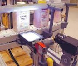
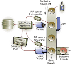
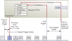
For high-speed applications with discreet parts, such as bottling, packaging lines, and label inspection, a photoelectric detector is the sensor of choice. Like optical encoders, photoelectric sensors have a photodiode detector and light source (see Fig. 1). As a product on the line approaches the inspection station, it breaks the light path between the detector and emitter, creating a signal that can be used for triggering the machine-vision measurement system, and/or for counting products. Products cannot overlap in this scenario, otherwise they will be counted as one object (see Figs. 2 and 3).
These sensors work with LED and laser emitters. LEDs cost less but disperse more, reducing the spatial accuracy of the photoelectric detector. Both LEDs and lasers can be combined with optical filters in front of the detector to counter the effects of ambient light on the photoelectric sensor, but lasers are more precise and make it easier to determine proper sensor and emitter placement during integration. This edge is even more appreciated when the vision system is installed as retrofit, and, instead of working in transmission, the system must operate in reflective mode with the addition of a retroreflector.
In transmission mode, the detector and emitter are placed on opposite sides of the product; however, this is not always possible during a retrofit. By placing a passive retroreflector opposite a combination detector/emitter, the light from the emitter travels across the inspection path and reflects back to the detector, eliminating the need for mechanical supports and power to the far side of the material-handling system.
Photoelectric sensors with special filters or wavelength-specific photoelectric sensors are sometimes required. Klein says, “A lot of companies use hot-melt glue for securing automotive and other parts, and you have to check that the glue is dispensing properly. This glue naturally fluoresces under ultraviolet (UV) light, and there are glue additives to increase the fluorescence. We can use a UV fluorescence sensor to check that the glue is being dispensed properly or to trigger a machine-vision inspection.”
FIGURE 3. Mini-PLC in ipd Vision Appliance uses first-in-first-out (FIFO) memory to track each part as it passes the machine-vision system. Inspection results are entered into the FIFO and at the inspection point. The part and its data in the FIFO are moved together so that when the part is detected by the sorting PiP, the system reads the inspection result from the FIFO and can activate a sorting mechanism to accept, reject, or recycle the part. Including mini-PLC electronics inside the vision system reduces latency and simplifies system integration.
Most machine-vision systems will use one of these three sensor types, but they are not the only nonimaging sensors available. Scales, conveyor stops, and other mechanical switches are also in use, but mechanical sensors increase the complexity and cost of ownership, and replacing these mechanisms usually requires stopping the production line.
Noncontact sensors, on the other hand, cost more but typically last longer and are easier to replace. In the end, sensor selection starts with the application and concludes with the customer’s comfort zone, preferred replacement parts, and the sensor’s usability.
Indexed assembly
In a typical dial- or index-table assembly-and-measurement application, a part approaches the first inspection station (#1). As the cam controlling the table movement approaches the first machine-vision station, a proximity switch located underneath the table near an optional locking collar with metal lobe (if cam does not have lobes already) comes near the proximity switch. The proximity switch confirms that it senses a “lobe” on the cam, indicating that the dial has reached a “dwell” point and is ready for an assembly operation.
The signal from the proximity switch is passed along a standard 24-V twisted-pair wire to the PLC controlling the table rather than directly to the machine-vision system so that the PLC can track each index step on the dial table and trigger machine vision system station #1 when the part under test reaches that index step. A second proximity switch located at machine vision station #1 confirms that a part is present in the inspection area.
The camera at machine-vision station #1 acquires an image of the part and determines orientation of the part for machining. The machine-vision system sends a serial signal back to the PLC telling it to index the table again to position #2, and the machine tool conducts its programmed operation on the part before sending another index signal to the PLC controlling the dial. The part passes to station #3 where a second camera measures the work of the automated machine station and determines if it meets customer specifications.
—R.W.H
Company Info
Allen-Bradley/Rockwell Autoon, Milwaukee, WI, USA www.ab.com
Banner Engineering,Minneapolis, MN, USA www.bannerengineering.com
BD Automation,Burnsville, MN, USA www.bdautomation.com
Classic Manufacturing, Oakdale, MN, USA www.classic-mfg.com
Coreco Imaging,St. Laurent, QC, Canada www.corecoimaging.com
ipd,Billerica, MA, USA www.goipd.com
Turck USA, Minneapolis MN, USA www.turck-usa.com


