Intuitive software speeds system development
Icon-based software tools make it easier and faster to build machine-vision systems.
By Andrew Wilson, Editor
Developers of machine-vision systems are faced with many choices when purchasing software. These range from developing proprietary object-oriented code that may or may not be hardware-specific, to using C-callable vendor-supplied libraries, to using the latest generation of icon-based tools. While each choice has its merits, systems designers are finding that graphical toolkits are easier to use, configure, and deploy, allowing complex image-analysis and machine-vision systems to be more easily integrated with motion-control and test-and-measurement equipment.
One reason for the popularity of an icon-based approach is the very nature of image processing. In many machine-vision applications functions are performed in a sequential manner. To properly count objects of certain sizes in an image, for example, captured images may first need to be thresholded, a blob analysis performed, and a plot of the number of pixels generated. Then it may be necessary to overlay blob data with a specific color, highlighting objects of a certain size.
Recognizing the nature of this data flow, software vendors now supply icon or glyph-based software that visibly describes the data flow by defining each algorithm or function as an icon or node that can be linked with other icons to perform specific functions. While such software may be useful for rapidly prototyping specific image-processing tasks, it is not a panacea for the development of complete systems.
Many machine-vision systems require more than simple image-processing tasks to be performed. They require the development of sophisticated user interfaces, often use specialized hardware such as linescan cameras with nonstandard interfaces, and must be integrated with data acquisition, motion control, and networked programmable logic controllers. In choosing software, developers must, therefore, also be aware of the graphical development tools supplied with the software and the hardware supported and, once developed, whether the software can be easily used with other development tools such as Microsoft Visual Studio.
One of the pioneers of graphical software development environments is National Instruments (NI). For years, developers of embedded systems have used the company’s flagship LabVIEW product to prototype and deploy systems for data acquisition, machine control, and machine vision. Using the concept of Virtual Instruments (VIs)-icons that perform specific tasks-the company’s IMAQ Vision module adds machine-vision and scientific image-processing capabilities to LabVIEW. With functions for gray-scale, color, and binary-image display, IMAQ vision’s image-processing VIs include functions for pattern-matching, shape-matching, blob analysis, gauging, and image-measurement functions.
To capture images from FireWire cameras, the company supplies its IEEE 1394 driver, relieving the systems integrator of integrating separate drivers when using FireWire cameras. Other types of cameras also can be integrated into IMAQ Vision-based systems by using drivers either supplied as dynamic link libraries (DLLs), .exe, files, or LabVIEW VIs. A complete list of NI-supported cameras can be found on the Web at volt.ni.com/niwc/advisor/camera_vision.jsp. For some embedded imaging applications, however, hardware-specific drivers must be purposely developed by the systems integrator or by third parties such as WireWorks West, a company that specializes in the development of device drivers for scientific and engineering applications.
ADDING DLLS
Experienced systems developers can use IMAQ Vision and LabVIEW to build systems with the image-processing functions supplied as VIs. For a certain class of machine-vision system, the developer simply requires higher-level operations such as part presence, edge detection, gauging, OCR, and pattern-matching to be performed. For these types of applications, the company’s Vision Builder for Automated Inspection allows images to be viewed and specific functions such as gauging to be graphically displayed on-screen.
Using a decision-making interface, the developer sets the parameters of images to be inspected and routs the results to any number of NI’s digital I/O products. Once built, the Vision Builder for Automation script can be converted to IMAQ Vision code, which can then be used to build a custom user interface or add measurement or automation functionality such as motion control or data acquisition.
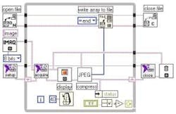
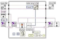
“An important benefit of using LabVIEW is the ability to call DLLs,” says Holger Lehnich of the Martin-Luther-University Halle-Wittenberg. There, Lehnich and his colleagues developed a digital video recorder based on LabVIEW. Because the standard VI from the IMAQ Vision Library -‘Write JPEG File’-was not fast enough to compress 768 × 576-pixel images in 150 ms, Lehnich used a DLL from Intel’s JPEG Library (IJL) that provides high-performance JPEG encoding and decoding of full-color and gray-scale images. “This DLL makes conversion to and from JPEG simpler by working on a DIB byte format and makes it easier to use for LabVIEW programmers than the Independent JPEG Group’s C code, since the input and output format in memory is in a standard Windows format,” he adds (see Fig. 1 on p, 43).
FIGURE 1. Researchers at the Martin-Luther-University Halle-Wittenberg have developed a digital video recorder based on LabView that incorporates Intel’s JPEG Library to provide JPEG encoding and decoding of full-color and gray-scale images.
Like LabVIEW, WiT from Coreco Imaging is a software package for developing image-processing applications that uses icons called igraphs. Each block in an igraph represents a function, typically an image-processing or analysis technique. To develop a specific application, the operator library of more than 300 processing functions can be linked to form igraphs that direct data from the output of one operator to the input of another.
Parameters for each operator can be changed with pop-up dialog boxes. For example, the convolution operator has a kernel editor for programming the coefficients. When the algorithm is complete, the igraph can be executed. WiT includes flow-control operators that perform loops and conditional branches and has operators for manipulating data, sorting data arrays, and performing string manipulations. To simplify development, igraphs can be nested and represented as new icons. Nested igraphs can then be executed and debugged in the same manner using the same tools as simpler igraphs.
Developers can create their own image-processing functions and add them to the library and develop custom user applications with Visual Basic or Visual C++. WiT can operate with live camera data through a frame-grabber interface or by reading image files from disk. To maximize real-time operation, WiT’s imaging libraries are optimized for multiple CPUs. In addition, WiT can distribute operator execution over distributed processing networks and embedded vision processors.
Hardware support includes the Viper, Mamba, PC-Series, Bandit II from Coreco, and DirectShow and TWAIN compatible devices allowing support of USB and FireWire cameras. Because of its open architecture, other cameras or data-acquisition devices can be added as required. An execution engine, called the WiT engine, can be used as either a DLL or ActiveX component permitting the creation of custom GUIs with Visual Basic or Visual C while using algorithms created with WiT to handle the image processing and data acquisition. Most igraphs can also be converted into C source code for inclusion in OEM applications.
SCALLOPING LACE
Developed and maintained by the Vancouver division of Coreco Imaging (formerly Logical Vision), WiT software has been used in a number of applications including the development at the University of Loughborough of an automatic system for scalloping decorative lace. “Lace scalloping involves the removal of a backing mesh from the main lace pattern to form a scalloped edge,” says Philip Bamforth, who developed the system. “Currently, almost all lace is either cut by hand with scissors or by mechanical cutting systems that require constant supervision to prevent problems such as snagging and tearing.”
Using a machine-vision system to identify the cutting line and a CO2 laser to cut the path at speeds up to 1 m/s, Bamforth’s automatic scalloping system is now being marketed by Shelton Vision Systems. “The imaging system was implemented using the WiT development environment,” says Bamforth.
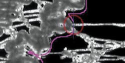
FIGURE 2. Automatic system for scalloping decorative lace uses machine vision to identify the cutting line and a CO2 laser to cut the path at speeds up to 1 m/s. The imaging system was implemented using the WiT development environment. Output from the machine-vision system shows the cutting path in purple with the current thread target identified by a crosshair.
“The use of the WiT system on a PC has allowed very rapid development times for many of the algorithms used. WiT together with Visual C++ gives developers a rapid development environment for image-processing algorithms.” To locate the ends of each thread, the machine-vision system uses a number of algorithms (see Fig. 2).
ARTIFICIAL EYES
Designed for developers of embedded video and image-processing systems, The MathWorks’ Video and Image Processing Blockset was announced in September (see Vision Systems Design, September 2004, p. 13). Designed to allow imaging engineers to build models, simulate algorithms and system behavior, generate C-code for deployment on programmable processors, and verify their designs within the company’s Simulink environment, The MathWorks Blockset supports the DM64x video development platform from Texas Instruments (TI). Using the blockset, developers can simulate and automatically generate floating- and fixed-point C code, migrating from floating- to fixed-point data types within the same model.
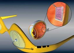
One of the early adopters of the technology is James Weiland of the Doheny Eye Institute at the University of Southern California. “We are working on real-time image processing with TI DSP (DM64x) as the target processor for a retinal-prosthesis project using the Video and Image Processing Blockset,” says Weiland. The current prototype consists of an external camera to acquire an image and electronics to process the image and transmit the signal to an implanted electronic chip on the retinal surface (see Fig. 3). “Ideally, an implanted chip would replace retinal photoreceptors on a one-to-one basis to provide nearly normal vision. In reality, it is impossible to replace all 100 million photoreceptors due to limitations in microfabrication,” he says.
FIGURE 3. James Weiland at the Doheny Eye Institute at the University of Southern California is developing a prosthetic retina. The current prototype consists of an external camera to acquire an image and electronics to process the image and transmit the signal to an implanted electronic chip on the retinal surface.
While current methods only permit 16 electrodes to stimulate the retina, this may be extended to 100 electrodes. “Even with 100 electrodes, visual input will be reduced from 100 rather than 100 million input channels. Because the initial prototype implant will most likely have fewer than 100 electrodes or pixels, a DSP will reduce a 480 × 640-pixel array into a 10 × 10 retinal stimulating electrode grid either through decimation or averaging. According to Weiland, more-advanced algorithms simulating retinal functions such as edge detection and motion detection also will be developed. Future implants will have more than 1000 electrodes on the retinal surface, a number that may place constraints on real-time image processing.
STERILE SYSTEMS
A Direct X-based development environment for image- and video-processing applications, the MontiVision Workbench from MontiVision Imaging Technologies can create imaging configurations that are exportable for subsequent integration into customized applications. Using the MontiVision Smart ActiveX-Control, developers are provided access to the interfaces and dialogs of the modules and video window for image display. Several modules are supported, including motion detection, blob analysis, morphological filters, and batch processing.
The software-development kit (SDK) supports DirectX-compatible and Windows-based video processing and display modules. Customized modules are created using the SDK, through Visual Studio 6 and Visual Studio.NET wizards. Monti- Vision’s modules are customizable via gra phical property dialogs and language-independent development techniques (COM). By acquiring images from third-party frame grabbers and FireWire and USB cameras, developers can access image data from video streams and evaluate and manipulate the image data directly.
Recently, MontiVision and Steribar Systems formed a partnership, combining Steribar’s Data Matrix decode and analysis software with MontiVision software for Data Matrix reading applications on surgical instruments. The result is a stand-alone 2-D Data Matrix reader that aids in tracking sets of surgical instruments through the decontamination processes. Barcode technology and software link each patient to individual instruments or instrument sets. This enables patients to be identified with bench-top autoclave cycle logs and the person responsible for processing the instruments to the procedure.
INTEGRATED PACKAGES
After acquisition of Khoros Pro from Khoral in May 2004, AccuSoft rebranded the product VisiQuest. Used in commercial, government, academic, and research environments, VisiQuest is also an icon-driven scientific computing software package that enables data- and image-analysis systems to be developed. Like other visual programming environments, developers can manipulate the more than 300 functions within the product to create programs. These glyphs represent operators, stand-alone programs written in C, C++, Java, or a scripting language that performs operations on an input image or dataset, producing an output image or dataset.
Connections between the glyphs represent the data flow between them. Advanced programming language constructs such as loops, procedures, and control structures complete the visual programming capabilities. In addition to writing visual programs using these operators, developers can use the VisiQuest software development environment to develop new operators. Once a visual program has been created, it can be compiled into a stand-alone program that can be executed without VisiQuest. According to Accusoft, future product introductions will combine VisiQuest’s visual programming environment with features of ImageGear, an imaging toolkit for .NET.
Depending on the level of sophistication required by the user, icon-based image-processing software can be used to successfully implement machine-vision systems. Software developers can use these icon- or glyph-based software development tools to describe data flows instead of writing code to perform each operation individually. And, thanks in large part to a host of PC development tools from Microsoft and others, these programs can be incorporated into more sophisticated systems that may combine data acquisition and process control.