Optical scanners enhance vision systems
New configurations expand optical and laser applications in food inspection, electronics, and medical imaging.
By R. Winn Hardin, Contributing Editor
The ubiquitous optical laser scanner has changed many things, from shopping to tracking business inventory. Recently, however, the relative low cost, ease of use, and reusability of radio-frequency-identification tags have given optical barcode scanners competition in traditional inventory-tracking applications.
Countering this trend are the sharp reduction in the price of lasers, both low-power reading lasers and high-power writing or welding lasers, reductions in the complexity of laser systems, and ongoing development of turnkey optical scanners. These turnkey systems combine optical, mechanical, and electronic functions in easy-to-use packages that enhance the resolution and flexibility of traditional automated optical inspection (AOI) systems in applications ranging from electronics to food processing and medicine.
SCANNER TYPES
"When laser scanning goes head to head with traditional imaging, laser scanning loses, unless it represents a unique way to acquire an image or picks up additional information, such as texture of an object at high speeds, that would not be easily available through conventional imaging techniques," explains Lincoln Laser vice president of operations Glenn Stutz. "There has to be a reason to accept the slight additional costs and moving parts that come with optical scanners."
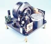
Optical scanners fall into three main categories: spinning polygon mirror scanners, resonant optical scanners, and galvanometer-based optical scanners. Spinning polygon mirrors move in a linear waveform, creating clean straight lines from a point of light that moves in one direction only and typically at a single scanning frequency. Resonant scanners can use a variety of actuators to create extremely small-form-factor scanners that typically follow a sinusoidal scan path common to display applications such as projection TVs. Galvanometers are limited-angle actuators that can move precisely within a 40° mechanical or 80° optical field of view and can be steered to any point within that field of view through the application of a positive or negative voltage—essentially a mirror attached to a servo or electric motor with electronic control.
"All of the scanning technologies have their strengths and limitations," says Red Aylward, president of Cambridge Technology. "Some markets are all galvanometers and others all polygons, but when it comes to machine-vision applications, all the optical scanning technologies share the market. Galvos can follow any waveform such as raster, vector, sinusoidal, and triangles, and can execute very precise constant-velocity positioning sweeps at application-defined rates and angles."
"Our galvo rates typically max out below the 2-kHz range," he adds, noting that polygons can spin very fast, achieve rates better than 30 kHz, but only go in one direction and are fixed in frequency. Resonant scanners can go at 8 kHz and greater, but integrators have to deal with the additional synchronization and system-timing and positioning- control issues between the sensor and the fixed bidirectional sinusoidal nature of the resonant scanner's positioning motion. In each of these technologies, the scanning system costs vary with the aperture and the performance required.
PERFORMANCE TO APPLICATION
Optical scanning applications in machine vision fall into two broad categories: imaging systems and laser scanning systems. The two can be combined coaxially using the same optical train when the application calls for high-resolution laser measurement and wide-area AOI, such as robot guidance.
Markus Guggenmos, founder and president of Arges, illustrates the point by describing a common robot-guidance application where an optical scanner must work in both imaging and beam-steering mode. "Take a scanning laser system mounted on the claw of a Kuka robot. The robot has a repeatability of 2 or 3 mm. Its job is to position a 6-kW fiber laser for welding, but the customer wants submillimeter accuracy. The only sensible solution is to first image the object through the scanner's optics with a vision system, find out the robot's true position relative to the weld line, and then compensate by offsetting the scanner to properly direct the beam" (see Fig. 1).
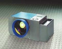
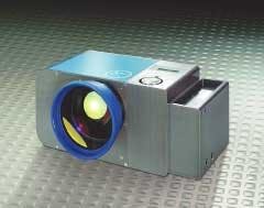
FIGURE 1. Arges Fiber Rhino three-axis optical scan head, with built-in vision module, galvanometer, and fiberoptic delivery system, is designed for end users who understand the machine-vision software environment and lasers, but lack expertise to handle optical scan-head design and integration.
Jim Shepard, who runs Arges-USA, adds, "A coaxial setup does have certain advantages because it takes into account the aberrations caused by lenses and other optics, while canceling a lot of the drift and misalignment features you might face by using separate mirrors for the laser and the optical inspection." Arges has developed its Fiber Elephant scan head with built-in vision module for these applications, including a recent application involving the welding of a rubber gasket in a cell phone.
The Arges Fiber Elephant system includes a galvanometer optical scan head, CCD sensor, and beamsplitter to allow both the laser and the CCD to use the same optical path. The customer can use a choice of machine-vision software and the built-in CCD sensor to acquire images of the gasket's position before welding. After determining the position, the galvanometer steers the fiber-delivered laser beam to weld 60 spots on the gasket in less than a second.
The system is triggered through the machine-vision software and serial control interface to randomly inspect samples of the welded gasket. Since optical scanners typically have a positioning depth upward of 16 or 18 bits, Shepard says, it is far easier to control the beam and camera using an optical scanner than placing the cell phone on slow-moving microscope stage. Also, by using a coherent illumination source with limited interference, Arges' Guggenmos adds, the vision system can resolve features up to four times smaller than the pixel size, or easily down to 1 µm in a 1-to-1 example (6 × 4-mm field of view and 640 × 480 pixel size at 10-µm pixel size).
Optical scanners do not need to use a laser to be effective. Cambridge's Aylward has sold several systems to the electronics-manufacturing industry that use a galvanometer to direct the field of view of a megapixel or greater, high-resolution CCD around a printed-circuit board to make coplanarity measurements of ball-grid array and other chip-scale packages. "By steering the camera around the board, you can apply your pixels to a small region rather than across the entire board or be forced to use multiple cameras for the same application," says Aylward.
Guggenmos notes that while replacing two cameras with one camera and one galvanometer scan head may not represent significant cost savings, the flexibility that a scanner adds to an imaging system can enhance the system's worth. "If you have multiple positions that you want to scan or flexible production lines that change on a daily basis, or if the positions that you want to check are not fixed but come from an algorithm or are randomly generated for quality assurances, then you can change your process in software without changing any hardware or adding cameras."
BIGGER IS BETTER
Sometimes breaking up the inspection area into various windows is not appropriate, such as in high-speed food-processing applications or the lumber industry. "Laser scanning is very useful in high-pixel-count applications where you would need to use multiple CCD cameras to achieve the same number of pixels. A laser scanner with an avalanche photodiode, silicon PIN photodiode, or photomultiplier tube is equivalent to a linescan camera," says Lincoln Laser's Stutz (see Fig. 2).
According to Stutz, unlike linescan cameras that can achieve 2000 lines/s, laser scanning systems can achieve 30,000 lines/s. This is due to the more intense laser light source—providing a larger light budget for inspections—and the faster readout times of high-gain photodiodes compared to the readout electronics of standard CCD linescan cameras, excluding specialized multitap sensor designs. "Multitap might go faster [than 2000 lines/s] but the question is what is their light budget? Laser scanners do not have to have high-output light sources that waste a lot of radiation and create a lot of heat. A laser puts the light right where you want it and at the frequency you want," says Stutz.
Lincoln has had success in high-speed sorting applications using changes in specular reflection to detect changes in texture, rather than using the shape or size of the objects under test, to sort fruit and vegetables from foreign objects. This approach requires significantly less processing power than a comparable imaging system facing the same task. Similar applications measure the differences in reflectivity of infrared laser light to separate organic from inorganic materials or to determine the location of knots in wood before trees are cut into boards, optimizing the usable product per tree.
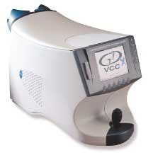
FIGURE 4. Laser Diagnostic Technologies GDx VCC provides glaucoma detection with laser scanning polarimetry, which measures the retinal nerve fiber layer in the eye by double-passing near-IR laser light through the layer and calculating the retinal thickness by the differences in the time of flight of the cross-polarized pulses.
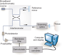
Infrared laser light and galvanometers are also enabling new medical imaging applications such as optical coherence tomography of the retina and other tissues (see Fig. 3). In human-vision applications, a galvanometer scans pulses of IR laser light across the back of the retina. Birefringence causes the single pulse to split into two oppositely polarized pulses. By determining the time of flight between the cross-polarized pulses, the imaging system can deduce the thickness of the retinal wall and determine if the tissue is degenerating long before the patient detects a loss of vision (see Fig 4).
By combining multiple scanners such as orthogonally spinning polygons, or placing a polygon scanner between a light source and a galvanometer, integrators are creating unique solutions that build on the strengths of AOI systems to provide greater functionality, cost savings, or both.
Company Info
Arges, Nabburg, Germany
Arges -USA, West Springfield, MA, USA www.arges.de
Cambridge Technology, Cambridge, MA, USA www.cambridgetechnology.com
Kuka-Roboter, Augsburg, Germany www.kuka-roboter.de
Laser Diagnostic Technologies, San Diego, CA, USA www.laserdiagnostic.com
Lincoln Laser, Phoenix, AZ, USA www.lincolnlaser.com
