USB 3 Vision: Extending camera to computer interfaces
Andrew Wilson, Editor
Officially ratified in January this year, the USB Vision standard is set to become one of the most popular interfaces for camera to computer connections. Indeed, numerous camera manufacturers have already announced cameras based upon the standard. To ensure that these cameras comply with the standard, the USB Vision Technical Committee of the Automated Imaging Association (Ann Arbor, MI; www.visiononline.org) has also developed a series of hardware and software tests to ensure these products conform to the USB 3 Vision standard.
Electrically compatible with the USB 3 standard introduced over five years ago, the USB 3 Vision standard supports a maximum throughput of 400MBytes/s over 10 times fast than USB 2.0. While the USB 3 Vision standard is electrically compatible with USB 3, the USB 3 Vision standard also includes device discovery, device control, event handling, and streaming data mechanisms that make USB 3 Vision suitable for machine vision applications. As importantly, the standard also specifies locking connectors which are necessary for the machine vision market but are not considered part of the USB 3.0 standard (see "USB3 Vision, Version 1.0", January, 2013, http://bit.ly/16LY803).
Connector types
In the USB 3 Vision standard, four types of connectors are specified: Standard-A, Standard-B, Powered-B and Micro-B connectors. While the most commonly used of these connectors is the flat rectangular Standard-A connector, USB 3.0 versions of the connector use nine pins to support the higher data rates of the USB 3.0 standard. Even though the USB 3.0 Standard A connector adds an extra five pins, careful engineering of the connector allows it to be plugged into either USB 2.0 or USB 3.0 receptacles that employ just four pins.
Standard A type connectors are designed to interface to host controllers and hubs, and since these host controllers (such as PCs) can be used to power peripherals, a second connector – the Standard B connector was developed to interface to peripheral devices. In the USB 3 Vision standard, two USB 3.0 Type B connectors are specified: the USB 3.0 Standard-B and USB 3.0 Powered-B connector.
Like the A type connector, the Standard B connector has nine pins to support USB 3.0 speeds but has different mechanical dimensions. Because of this, USB 3.0 Standard-B plugs can only be used with USB 3.0 Standard-B receptacles. However, USB 3.0 Standard-B receptacles can accept either USB 3.0 or USB 2.0 Standard-B plugs.
In the past, peripherals such as cameras connected to a host computer could draw 900mA from the host port, but attached peripheral devices power could not power other peripherals. Because of this, the USB standards committee introduced USB 3.0 Powered-B connectors. With two additional pins to provide power – for a total of eleven pins – these Powered-B connectors are identical in dimension to Standard B connectors. However, using the extra two pins, a powered peripheral device with a Powered-B connector can be used to supply 1000mA current to another peripheral device. Because of its design, the USB 3.0 Powered-B receptacle can accept both Standard-B and Powered-B connectors.
To interface to peripheral devices such as cameras, the Micro-B connector will most often be used. USB 3 Micro-B connectors consist of a USB 2 portion and a USB 3.0 portion, allowing them to be backwardly compatible with USB 2.0 Micro-connectors.
While relatively, low cost unshielded twisted pair (UTP) cable could be used to connect peripherals using the USB 2.0 standard, the higher speeds required by USB 3.0 necessitate the use of a shielded differential pair (SDP, twisted or twinax) cable. And, while the USB 2.0 standard defines a maximum computer to peripheral cable distance of 5m, the maximum length cable length for USB 3.0 connections is not specified in the USB 3.0 standard. Because of this, 5m passive cabling lengths are most commonly offered by cable manufacturers.
Such USB 3.0 Vision certified passive cables are available from a number of companies including Alysium-Tech (Nuremberg, Germany; www.alysium-tech.com), Components Express Inc (CEI; Woodridge, IL; www.componentsexpress.com), Intercon 1 (Baxter, MN; www.intercon-1.com) and Newnex Technology Corp (Santa Clara, CA; www.newnex.com). Having said this, Alysium-Tech has tested passive USB 3.0 Vision industrial cables with cameras from IDS Imaging (Obersulm, Germany; www.ids-imaging.com), Point Grey (Richmond, BC, Canada; www.ptgrey.com) and Ximea (Münster, Germany; www.ximea.com) running at distances of up to 8m.
Active cables
To extend these distances further, many companies have developed active electrical cables, active optical cables and active repeaters. Using driver/equalizer chipsets to overcome the attenuation, crosstalk, and group velocity distortion effects of passive cables, active electrical cables are supplied in a number of different configurations. These include cables that embed the signal conditioning circuitry into the cable connector and cables that incorporate in-cable repeaters.
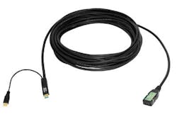
To address the machine vision market, Icron has now teamed with Components Express Inc to develop a USB3 vision-compliant 15m USB 3.0 active extension cable. While Icron will brand the cable as the USB 3.0 Spectra 3001-15, CEI will offer the product as the BIT MAXX Extreme USB 3.0 (Figure 1).
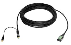
Rather than embed circuitry into the connector, the FireNEX-uLINK USB 3.0 active repeater from Newnex takes a similar approach to that used by CEI in its Bit Maxx Camera Link extender, embedding active circuitry in an enclosure on the length of the cable. Powered from the USB bus, the FireNEX-uLINK allows distances of 12m in length to be achieved (Figure 2).
Fiber-optic interfaces
In many machine vision applications, however, even distances of up to 12m will not be sufficient. In such cases, systems developers can turn to fiber optics to extend camera to computer interfaces even further. In applications such as medical imaging such fiber connections are especially useful since any electromagnetic induction radiation emitted from an external source will not degrade the optical signal.
When implementing such systems either active optical cables (AOCs) or optical extenders can be used. In both approaches, data from a camera is first converted into an optical signal, transmitted over the fiber interface and re-converted to an electrical signal at the computer. If either an active optical cable or an optical extender is used to increase the camera to computer distance, the camera will require an external power source since electrical power cannot be transmitted over the optical interface.
Today, a number of companies such as Universal Microelectronics Co (UMEC; Taichung, Taiwan; www.umec-web.net) and Unibrain (San Ramon, CA; www.unibrain.com) offer both active optical cables that integrate optical transceivers into the connector housings. In the design of its Thumb ONE USB 3.0 AOC, for example, UMEC has integrated the VO510 5-Gigabit Optical Transceiver from VIA Labs (New Taipei City, Taiwan; www.via-labs.com) to extend the USB 3.0 transmission distance up to 100m (330ft) with optical fibers.
Stand-alone extenders
External optical extenders are also available from such companies as Newnex and Icron. Like AOCs, these also allow transmission distances of up to 100 m to be achieved. Consisting of a pair of standalone units for electrical/optical and optical/electrical conversion of USB data, the Newnex FireNEX-5000, for example, includes both an upstream and downstream unit and a single power supply. While the host (upstream) device can be powered by the host, the downstream unit requires an external power source. The USB 3 port on this downstream unit can then be used to power peripherals such as cameras.
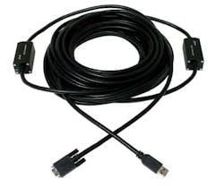
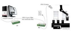
Like Newnex, Icron also offers external optical extender to extend transmission distances of USB 3.0 computers and peripherals. Two USB 3.0 100-m fiber extenders – the USB 3.0 Spectra 3022 and its OEM equivalent, the USB 3.0 SP3022 – can extend USB 3.0 to 100 m over multimode fiber-optics (Figure 3). Both are two-port extenders that comply with the AIA USB3 Vision standard and feature locking USB and power connectors, and optional mounting rack support for industrial machine-vision applications such as factory automation. In July this year, the company announced that the extenders had been successfully tested with VGA to 5M pixel cameras from The Imaging Source (Bremen, Germany; www.theimagingsource.com).
More speed and power
Just as the adoption of the GigE Vision standard eased the integration tasks of vendors seeing to develop machine vision systems, so too will the introduction of the USB 3 Vision Standard. Like GigE Vision, however, the USB 3 Vision standard will likely be extended to incorporate faster data rates.
Already, the USB Implementers Forum (USB-IF; Portland, OR; www.usb.org) has announced that updates to the USB 3.0 standard will include a new specification to double the data throughput performance using new cables that are backwardly compatible with existing USB connectors and cables. The USB-IF has also announced a USB Power Delivery specification that will provide a single cable for data and power delivery of up 100W.
Companies Mentioned
Automated Imaging Association
Ann Arbor, MI
www.visiononline.org
Alysium-Tech America
San Francisco, CA
www.alysium-tech.com
Components Express Inc (CEI)
Woodridge, IL
www.componentsexpress.com
Icron Technologies Corp
Burnaby, BC, Canada
www.icron.com
IDS Imaging Development Systems GmbH
Obersulm, Germany
www.ids-imaging.com
The Imaging Source
Bremen, Germany
www.theimagingsource.com
Intercon 1
Baxter, MN
www.intercon-1.com
Newnex Technology Corp
Santa Clara, CA
www.newnex.com
Point Grey
Richmond, BC, Canada
www.ptgrey.com
USB Implementers Forum
Portland, OR
www.usb.org
Unibrain
San Ramon, CA
www.unibrain.com
Universal Microelectronics Co (UMEC)
Taichung, Taiwan
www.umec-web.net
VIA Labs
New Taipei City, Taiwan
www.via-labs.com
Ximea
Münster, Germany
www.ximea.com
For more information, please visit the machine-vision software section of the Vision Systems Design Buyer's Guide (http://bit.ly/IJq0dP).
Vision Systems Articles Archives


