Applying ultraviolet lighting in machine vision applications
For developers inspecting plastics, paints, and labels, ultraviolet (UV) illumination reveals defects that cannot be revealed with visible light.
Matt Pinter
Many machine vision systems use visible 390-700 nm LED lighting components with which to illuminate products. While designers of such systems have applied these most effectively, there is an increasing demand to inspect products such as plastics, paints, printing inks and dyes that can benefit from illumination in the ultraviolet (UV) spectrum. In the past, such tasks were limited by the cost of UV light sources. Now, however, with the advent of lower-cost UV LED illumination, these applications are becoming more affordable.
UV is electromagnetic radiation with a wavelength from 10-400nm, that is classed into three different bands. Between 300-400nm, the band of the spectrum is known as the near-UV band and is divided into the UV-A (315-400nm) and UV-B (280-315) sub-bands. Below 300 nm, the UV-C band covers wavelengths from 100-280nm. In machine vision applications, wavelengths in the UV-A band, most notably at 365nm and 395nm wavelengths, are most commonly used.
UV light can be used in machine vision applications to detect features that cannot be detected using visible light. Since UV light is absorbed by many materials, it is possible to capture an image of the surface of a product and, because it has a shorter wavelength than visible light, it will be scattered by surface features on the product.
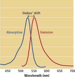
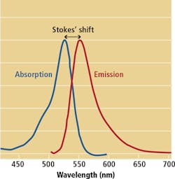
UV lighting can be applied in machine vision systems in two different ways. In reflected UV imaging applications, UV light is applied to the object and captured using a monochrome or color camera that is UV sensitive. In UV-fluorescence imaging, the surface of the object is again illuminated with UV light. In products such as paints, plastics, printing inks and dyes that have optical brighteners added to them, these fluorescent materials will absorb the UV radiation and then re-radiate a longer diffuse wavelength. The difference in wavelength between positions of the band maxima of the absorption and emission spectra are known as Stokes shift (Figure 1).
Fluorescence applications
Which UV light source and camera can be used in a particular application is often a matter of trial and error. Having said that, in UV fluorescence applications, applying as much light as possible to the part is important since the emitted light has a longer wavelength and therefore lower energy than the absorbed radiation. Using a color band-pass filter that allows only a portion of the spectrum to pass is also essential.
The reason for requiring such band-pass filters is that many of today's CCD and CMOS-based cameras have significant UV sensitivity. When used in UV fluorescence applications, therefore, interference between the UV light source and the visible fluorescence may occur. To overcome this, UV blocking filters can be used to prevent UV light from interfering with the desired wavelength required to be captured by the camera's image sensor. In a typical fluorescence application, where cyan is often the color emitted, a 470nm or 505nm band pass filter will pass the light or wavelength of cyan and block all other wavelengths, thus limiting unwanted colors and ambient light in the image. The most common band-pass filters for UV are BP470, BP505, BP525, BP590 and BP635. In fluorescence applications for machine vision, the most often used is the BP470, a 470nm band-pass filter that, when used with a greyscale or color camera will enhance the contrast of captured images.
Although there are a number of LEDs that emit light in the UV-A, UV-B and UV-C bands, in many machine vision applications, wavelengths of 365nm and 395nm are most commonly used. However, since which wavelengths will be most effective can only be judged by illuminating the product to be tested, Smart Vision Lights has developed a color box tester that allows designers to illuminate their parts with both 365nm and 395nm and understand which performs most effectively (Figure 2).
As an example, a manufacturer of diapers wished to inspect whether stitching had been correctly applied. While the stitching thread fluoresces, the UV wavelength used to produce the highest contrast visible image was not immediately apparent. While a color image could not reveal the stitching (Figure 3 left), illuminating the diaper with a 365nm wavelength (Figure 3 middle) provided more contrast than using a UV light at a wavelength of 395nm (Figure 3 right). Equally important was the choice of the UV filter used. If no filter is used, then the captured image cannot reveal the stitching (Figure 4 right). However, by using a BP470 filter, the stitching within the diaper is exposed (Figure 4 left).
Since the correct choice of filter is important, Smart Vision Lights has developed a filter kit for systems developers. This contains seven dichroic filters-used to selectively pass light of a small range of frequencies while reflecting other frequencies-two color pass filters ranging from 470-850nm, and a polarizer filter. The 27mm filters are supplied with two adapter rings of 25.5mm and 30.5mm, and transmission charts detailing the specifications of each filter polarizer.
Reflected UV
While UV-fluorescence imaging is used in many applications, reflected UV imaging-where no fluorescence occurs-can also reveal product defects. Here, the UV light is again used and the reflected UV light captured. In an application to detect air pockets on product labels, for example, UV illumination can be used to enhance any air pockets that may be present (Figure 5).
Such illumination may be an expensive proposition for some applications, however. To highlight the glue on envelopes, for example, may require a UV light of 280nm. Since the glue absorbs 280nm wavelengths, it will appear black in the reflected image (Figure 6). However, such 280nm UV LEDs are low-efficiency and at present cost upwards of $20 each. Thus, to produce enough light may require hundreds of such LEDs.
Having said that, many of the latest high-current LEDs that operate over longer wavelengths are now available in up to 10W packages and feature an increase in light output of between 10-30x those of previous generations. Such UV high current LEDs can also be strobed to increase light output - a factor important in high-speed machine vision applications. A further advantage of such UV high current LEDs is that they can be designed with parabolic reflectors and lenses to produce a concentrated, focussed light pattern and can thus be used at longer working distances.
While still more expensive than their visible LED illumination counterparts, UV lighting is now being deployed in many industrial inspection applications both in fluorescence and reflected UV imaging modes. While still in its infancy, the decreasing cost of UV LEDs will lead to new applications as developers integrate UV lighting, off-the-shelf cameras and machine vision software in their production environments.
Matt Pinter, Director of Engineering, Smart Vision Lights (Muskegon, MI, USA;www.smartvisionlights.com)


