How to develop a low-cost 3D scanner using structured light
Develop a 3D Structured Light Scanner for Low Cost
Structured light has become a prominent 3D surface measurement technique that is acknowledged for its high speed and accuracy. As the essential component of any structured light scanner, the industrial and scientific light engines are usually either quite expensive or have low brightness. As such, many hobbyists employ commodity projectors (bit.ly/VSD-SL3D). With a large diversity of commodity projectors available on the market, scanners of different scales can be built, ranging from pico projectors to theater projectors with the size of target objects ranging from several millimeters to several meters.
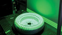
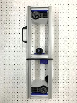
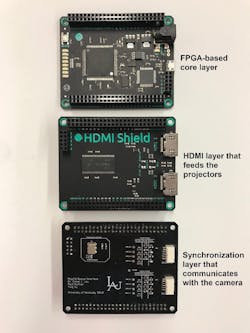
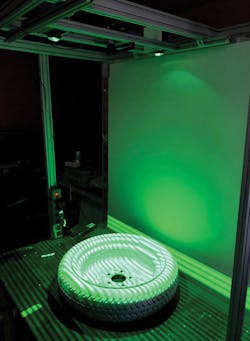
The principal difficulty of making structured light scanners with commodity projectors is to synchronize the graphics interface and the camera over HDMI. Because the instantaneous output of the HDMI port is unpredictable, an uncertain number of irrelevant frames could be inserted before the expected video frame is displayed, which makes it almost impossible for the camera to correctly capture the sequence of structured light patterns in an efficient way. Fortunately, with the dearth of FPGA development boards that have single or even dual HDMI ports, it is now possible to overcome this obstacle. One such FPGA module, used as part of this research, is the Xilinx (Santa Clara, CA, USA; www.xilinx.com) Spartan 6-based Mojo board, by Alchitry (Littleton, CO, USA; www.alchitry.com) or the Xilinx Artix 7-based Mimas A7 board by Numato Systems (Bengaluru, Karnataka, India; www.numato.com).A team from the Department of Electrical and Computer Engineering, University of Kentucky, has developed FPGA-based projector controllers to build industrial-quality 3D scanners using commodity projectors. As featured below, one such system is a dualprojector structured light scanner composed of two Optoma Corporation (New Taipei City, Taiwan; www.optoma.com) ML750ST projectors, each of which has 500 lumens and a projection area with an approximately 36” diagonal. In addition to the FPGA-based controller, the system also features a Basler (Ahrensburg, Germany; www.baslerweb.com) acA1920-150uc USB 3.0 camera, which features the 2.3 MPixel PYTHON 2000 global shutter CMOS sensor from ON Semiconductor (Phoenix, AZ, USA; www.onsemi.com) and a 150 fps frame rate.
The controller supports two working modes depending on the source of the structured light patterns. One mode internally generates the structured light patterns using the FPGA, while the other passes through the structured light patterns from the graphics interface on a PC, which could range from an Intel (Santa Clara, CA, USA; www.intel.com) Core i5 PC, off-the-shelf laptop, NVIDIA (Santa Clara, CA, USA; www.nvidia.com) Jetson, and even a Raspberry Pi (www.raspberrypi.org). When generated internally, Line 2 of the camera is configured as programmable output and is set high by the operator. The FPGA then sends structured light patterns to the projector and triggers the camera on the corresponding vertical syncs. Upon completing a scan, the operator sets Line 2 of the camera to low, telling the FPGA to stop sending structured light patterns and sending all black patterns instead.
When passing HDMI video from the host PC to the projector, Line 2 is still set low by the operator while patterns from the PC are passed through the scanner to the projector. The difference here is that the FPGA reads the red channel of the top-left pixel as a one byte of identification data indicating the number of the frame. By reading this top-left pixel as a handshake, the FPGA can decide if and when to trigger the camera with vertical syncs.
In this way, the operator can synchronize their pattern set to the camera without any loss of video and without dealing with the potential replication of frames by the graphics interface. There is no specific requirement for the graphics interface. Most PC graphics interfaces should work as long as they support OpenGL SL 3.3 or higher. Besides conducting the handshake for the system synchronization, the software running on the PC also sets up parameters under which the camera operates, such as exposure time, trigger source, resolution, etc.
In the 3D scanner, the projectors run at 120 fps using either an 8 or 24 frame structured-light sequence, depending on the required scan accuracy. The system can make 5 to 15 scans/second, and according to our experimental data, the scanner achieves a scanning accuracy with less than 2 mm standard deviation at 1 m range in its 5 scans per second mode.
For developers or designers interested in assembling their own scanner, sample project files have been made available at bit.ly/VSD-3DSL.
Ying Yu is a PhD student, and Daniel L. Lau is a Kentucky Utilities Professor and Certified Professional Engineer. Both are with the Department of Electrical and Computer Engineering, University of Kentucky (www.uky.edu).


