Understanding the latest in high-speed 3D imaging: Part one
Many companies developing 3D imaging products today refer to the product as fast or high-speed. While true in many cases, it is not always perfectly clear what high-speed really means, or what you can actually do in the real world with a given product. The following article helps shed light on some of the latest high-speed 3D technologies, and what these speeds really mean.
Time of Flight
One recent popular technology, Time of Flight (ToF), works by illuminating a scene with a modulated light source and observing the reflected light. The phase shift between the illumination and the reflection can be measured and translated to distance. In some devices, a pulse-based measurement technique is implemented.
Having first introduced ToF-based products several years ago, Odos Imaging (A Rockwell Automation company; Edinburgh, UK; www.odos-imaging.com) offers the Swift-G camera. Designed for applications including logistics (pallet management, palletization/depalletization), dimensioning and profiling, and factory automation; this ToF camera features 640 x 480 resolution and can reportedly capture dynamic scenes without artifact at 44 fps. Additionally, the camera has an integrated lens and illumination (Seven 850 nm LEDs), working distance of up to 6 m, and achieves a speed of 44 profiles/s.
Newly-available from LUCID Vision Labs (Richmond, BC, Canada; www.thinklucid.com) is the Helios Time of Flight camera, which features the Sony (Tokyo, Japan; www.sony.com) DepthSense IMX556PLR back-illuminated image sensor, delivering 640 x 480 resolution at a 6 m working distance using four 850 nm VCSEL laser diodes. The camera offers a 30 fps frame rate and targets robotic navigation, 3D inspection, and logistics automation such as bin picking and package dimensioning.
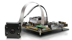
In addition, LUCID also recently introduced the Helios Flex 3D camera module for embedded vision systems (Figure 1) which is designed to be connected to an NVIDIA (Santa Clara, CA, USA; www.nvidia.com) Jetson TX2. The 3D camera module streams raw data via MIPI connection at 60 fps, with depth information processed on the TX2 module using LUCID’s Arena software development kit.
Basler (Ahrensburg, Germany; www.baslerweb.com) also designed its blaze ToF camera around the same sensor from Sony. Scheduled for series production in December 2019, this camera uses VCSEL laser diodes (NIR range, 940 nm), and offers a working distance of up to 10 m and a frame rate up to 30 fps. On an assembly line, this camera can measure 30 objects in succession in one second, according to the company.
The company offers another ToF camera based on a 645 x 480 Panasonic (Osaka, Japan; www.panasonic.com) sensor. The ToF camera uses pulsed light from infrared LEDs and offers a frame rate of 20 fps and working range of up to 13 m. Both cameras target applications such as freight dimensioning, palletizing, item counting, pallet positioning, and autonomous vehicles.
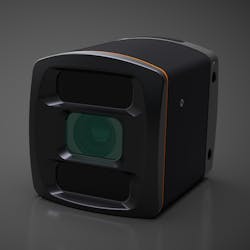
Offering a range of different models is ifm efector, inc. (Essen, Germany; www.ifm.com), which designed its 3D ToF cameras (Figure 2) for applications including packaging, storage and materials handling, airport logistics, robotics, and collision avoidance. These cameras feature an active infrared light source for illuminating a scene and offer a maximum reading rate of 50 Hz. Camera models are designed to be used both indoors (352 x 288-pixel resolution, 8 m range) and outdoors (64 x 16-pixel resolution, 30 m range) and come with a variety of opening angles.
“With our Time of Flight cameras, measuring 120 boxes per minute is feasible, while cases can be inspected for completeness at a rate of more than 240 per minute,” says Garrett Place, Business Development, Robotics Perception, ifm efector, inc.
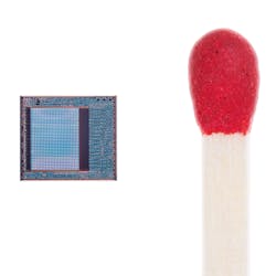
Owned by ifm efector, inc., PMD Technologies (Siegen, Germany; www.pmdtec.com) developed a CMOS 3D ToF sensor (Figure 3) based on its own pmd pixel matrix in collaboration with Infineon Technologies (Neubiberg, Germany; www.infineon.com). The REAL3 ToF sensors, sold by Infineon, feature resolutions of 224 x 172, 352 x 288, and 448 x 336, with higher resolutions coming out in 2020.
PC-based development kits are available directly from PMD Technologies. The picoFlexx module features the 224 x 172 sensor, frame rates up to 45 fps, and a measurement range of 0.1 to 4 m, while the Monstar module features the 352 x 288 sensor, frame rates up to 60 fps, and a measurement range of 0.5 to 6 m. Development kits for embedded systems will be available in early 2020.
For consumer electronics and mobile designs, pmd/Infineon-based depth modules are available from a number of companies, including LG Innotek (Seoul, South Korea; www.lginnotek.com/en) which provided the ToF module for the 3D face identification in the LG G8 mobile phone launched in early 2019. More mobile phone designs with pmd/Infineon depth modules are expected in 2020.
“PMD and Infineon’s focus is bringing 3D imaging to mass market devices such as mobile phones, IoT devices, and consumer robotics,” says Mitchell Reifel, VP Business Development and Sales, PMD Technologies. “Just a few years ago 3D imaging devices were the size of a brick, but today we are providing 3D modules the size of a thumbnail that provide high integration, low power, and small form-factors.”
With its Visionary-T and Visionary-T AP (programmable) series, SICK (Waldkirch, Germany; www.sick.com) also offers a range of Time of Flight 3D-snapshot cameras. These Gigabit Ethernet cameras use infrared light (LED, 850 nm) and can provide up to 50 3D images/per second at 144 x 177 pixels. These cameras suit applications such as collision warning, object detection, and depalletizing.
When discussing Time of Flight, Microsoft’s (Redmond, WA, USA; www.microsoft.com) second and third generation Kinect cameras may be the most recognizable examples of the technology. The third and most recent version, the Azure Kinect DK, features a 1 MPixel ToF depth sensor that provides 640 x 576 or 512 x 512 at 30 fps, or 1024 x 1024 at 15 fps. It also has an RGB camera based on an OmniVision Technologies’ (Santa Clara, CA, USA; www.ovt.com) OV12A10 12 MPixel CMOS rolling shutter sensor, which features a 30 fps frame rate at full resolution.
The Azure Kinect device, according to Microsoft, was designed to easily synchronize with multiple Kinect cameras simultaneously and to be integrated with Microsoft’s Azure cloud services, including Azure Cognitive Services which can enable the use of Azure Machine Learning. The camera, according to Microsoft, targets applications including physical therapy and patent rehabilitation, inventory management, smart palletizing and depalletizing, part identification, anomaly detection, and incorporation into robotics platforms.
How to interpret 3D ToF speeds
In all cases, Time of Flight cameras basically deliver a single frame of 3D data at whatever a company lists for that camera’s frame rate. Because of this technique, every frame produces an immediate 3D image. However, when it comes to the number of parts or objects that a camera can inspect per minute or second, or the number of 3D results the cameras deliver per minute or second, processing time must be taken into consideration. Just because a camera has a frame rate of 50 fps does not mean that the camera can inspect 50 boxes or parts per second, other than in cases such as guidance or interference avoidance for autonomous robots/vehicles, according to David Dechow, Principal Vision Systems Architect, Integro Technologies.
“Processing of 3D Time of Flight images is done either in onboard camera firmware or an external processor like a PC,” he says. “Depending on the amount of processing required, the actual capability of a camera in industrial applications in terms of how fast it can produce results will vary widely application to application.”
3D image analysis functions in the software take time, making it difficult for the software to keep up with the frame rate of the camera in most industrial applications. While frame rate is still important, in most applications it will not be realistic to keep up with a given ToF camera’s image acquisition rate, explains Dechow.
Laser-based techniques
Another active 3D imaging technique, triangulation, involves the use of lasers where a 3D laser scanner projects a laser onto the surface of an object and the camera captures the reflection of that line on the object’s surface. Through triangulation, the distance of each surface point is computed to obtain a 3D profile or contour of the object’s shape. Laser-based 3D techniques require many individual images, each containing just one line of the object being inspected, to create a complete 3D image of the object or features requiring inspection. As a result, laser-based techniques will be slower overall than Time of Flight, but faster than some structured light techniques.
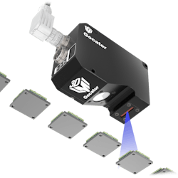
LMI Technologies (Burnaby, BC, Canada; www.lmi3d.com) uses this technique in its Gocator 3D laser profilers. While the company’s G1300 series achieve raw scan speeds of 32 kHz, the Gocator 2500 series (Figure 4) lists a complete inspection speed of 10 kHz, meaning scanning, measurement, and control of a single profile (one image line) all onboard the sensor, at a speed of 10 kHz, according to the company.
Keyence (Osaka, Japan; www.keyence.com) offers several 3D laser profilers geared toward 2D and 3D inline measurement and inspection. The lineup, according to the company, enables users to select the sensor and controller that will best fit an application’s technical specification and budget requirements. Both the higher resolution LJ-X series and higher speed LJ-V series can be paired with any of three controllers (2D/3D, 2D, and raw data output). This configuration supports quality control and process improvement in applications such as weld/bead inspection, flush and gap measurements, or 360° defect detection.
Both the LJ-X and LJ-V series incorporate blue, class 2M lasers (405 nm) combined with a controller unit designed to process data and output judgement values at high speed. The systems are capable of sampling speeds up to 4 kHz and 64 kHz respectively.
In its ScanCONTROL series of 3D laser scanners, Micro-Epsilon (Ortenburg, Germany; www.micro-epsilon.com) offers models that reach speeds of up to 10 kHz. Offered in compact, high-speed, and smart versions, these scanners are available with red (658 nm) lasers or blue-violet (405 nm) lasers and offer measuring rates of up to 5,500,000 points/s and x-axis resolution up to 2,048 points. Example applications provided by the company include defect recognition on worktops, gap measurements on a car body, profile measurements on brake disks, weld seam profile measurement, and adhesive bead inspection.
In its DS1000 3D displacement sensor series, Cognex (Natick, MA, USA; www.cognex.com) offers three models, the DS1050, DS1101, and DS1300, which are based on the same design but offer varying field of view (near and far), clearance distance, measurement range, and X and Z resolution. DS1000 laser scanners offer a scan rate of up to 10 kHz and target applications including automotive, electronics and consumer products, and food and pharmaceutical inspection. Cognex also offers the DSMax 3D laser displacement sensor, which reaches scan rates of up to 18 kHz and acquires 2,000 profile-point images within a 31-mm field of view. The DSMax sensor targets the inspection of very small parts, such as electronic components containing highly reflective or dark features.
In its TriSpector1000 and TriSpectorP1000 (programmable) 3D line scan sensors, SICK offers several models available with varying maximum height ranges, window material types, and widths at maximum operating distance. The TriSpectorP1000 sensors target applications including 3D robot guidance, profile verification, edge and surface defect detection, and bead inspection, while the TriSpector1000 sensors suit quality control in consumer goods, box integrity, and product dimensioning in food processing applications. Both series use visible red-light lasers (660 nm) and achieve scan/frame rates of 2,000 3D profiles/second.
Designed for use with separate sheet of light lasers, the Ranger series of 3D cameras from SICK feature the MultiScan tool for simultaneous measurement of 3D shape, contrast, color, and scatter. Ranger 3D cameras target applications including high-speed 3D inspection, tire geometry inspection, color and 3D tray inspection in solar cell inspection, and timber measurement.
The newest Ranger camera, the Ranger3 series, offers a compact version of the technology with its V3DR3-60NE31111 model. This 77 x 55 x 55 mm camera is based on a CMOS image sensor from SICK and can process its full frame imager (*2560 x 832) pixels to create one 3D profile with 2560 values in 7 kHz. The GigE Vision, GenICam-compliant camera also processes up to 15.4 Gpixels/second. Ranger3 cameras, according to the company, suit such applications as electronics and PCB inspection, tire quality control, and packaging and in-line food quality control.
Additional laser-based 3D sensors offered by SICK include the Ruler E line scan sensor, which uses a visible red-light laser (660 nm ± 15 nm) and achieves a scan/frame rate of 10,000 3D profiles/second.
Designed for use with separate lasers, the 3D sensors of the C5 series from AT – Automation Technology (Bad Oldesloe, Germany; www.automationtechnology.de) offer 4K UHD resolution and collect 3D data at speeds of up to 200,000 profiles/s. They feature integrated control for external illumination, an integrated Scheimpflug adapter, and a GigE Vision interface as well as 3D scan features such as auto-start, automatic area of interest (AOI) tracking, and multiple AOIs.
The 3D sensors of the C5-CS series combine 3D technology and laser electronics in a compact IP67 housing. They use a CMOS image sensor, FPGAs, and integrated 3D evaluation algorithms. C5-CS sensors also reach profile speeds of up to 200 kHz, a profile resolution of up to 4096 points/profile, and they provide the same 3D scan features as C5 sensors. The detector and optics are arranged according to the Scheimpflug principle. Additionally, the factory-calibrated C5-CS sensors offer a GigE Vision interface and a range of models available with either blue lasers (405 nm, class 2M, 3R, 3B) or red lasers (660 nm, class 2M, 3B).
The recently-launched 3D sensors of the MCS series provide the same equipment and performance as C5-CS sensors, but feature a modular concept which enables users to configure the devices to suit individual applications. All 3D sensor models, according to the company, suit applications such as printed circuit board inspection, weld seam inspection, tire inspection, adhesive bead inspection, ball grid array inspection, and wood surface inspection.
How to interpret laser-based 3D speeds
Laser-based 3D speeds are slightly less straightforward than those of the Time of Flight cameras. Comparing the speeds of the two techniques is possible, however.
“Comparing the speeds of a 640 x 480 Time of Flight camera to laser-based 3D techniques requires calculating how many lines and how long it would take to get 480 lines using this technique,” says Dechow.
Regardless of what a company lists as a speed for its 3D sensors, whether acquisition or acquisition and processing, one constant in laser-based techniques is that these sensors put together a contiguous image by scanning one line of information at a time, which is vitally important to keep in mind when considering the speeds of such sensors in the context of individual application requirements, explains Dechow.
Part two of the article, on page 33, looks at some of the 3D structured light products available today, as well as a unique technology called line confocal imaging, which was designed to overcome the limitations of other technologies with transparent materials and/or glossy surfaces.
This story was originally printed in the November/December 2019 issue of Vision Systems Design magazine. Part two of this article may be read here.*Editor’s note: The print version of the article lists the sensor resolution of the V3DR3-60NE31111 Ranger3 camera as 832 x 2560, but the correct resolution is 2560 x 832.
About the Author

James Carroll
Former VSD Editor James Carroll joined the team 2013. Carroll covered machine vision and imaging from numerous angles, including application stories, industry news, market updates, and new products. In addition to writing and editing articles, Carroll managed the Innovators Awards program and webcasts.


