A Tier 1 global leading manufacturer produces foam for the automotive industry. Produced and processed into lengths thousands of feet long by 80in wide and 0.5in thick, this foam is then shipped to customers that then laminate a fabric onto the foam. This is then formed into automotive headliners before being shipped to the automobile manufacturer.
"Before the fabric can be laminated onto the foam, however," says Craig Borsack, President of G2 Technologies (Apex, NC, USA;www.g2tek.com), "the foam must first be inspected to check for the presence of tears, cracks, holes or grease stains that would impact the visual integrity of the laminated headliner, making it look misshapen or preventing the fabric from adhering as it should." In the past, this inspection was performed manually and relied on the ability of inspectors to recognize such defects.
"However, because the foam is moving at approximately 600ft per minute along a web, inspectors could only identify gross defects such as large tears or holes and significant stains. For a company committed to delivering a high-quality product, the possibility that defects were missed during manual inspection was a concern. If defective foam reached an end-customer, it was often returned and scrapped at the manufacturer's expense, threatening both the manufacturer's bottom line and its reputation," says Borsack.
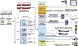
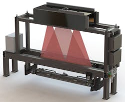
To allow defects as small as 0.5mm to be detected, G2 Technologies leveraged their 4th generation web inspection platform that uses a number of off-the-shelf components to perform the task (Figure 1). To inspect the foam across the 80in field of view (FOV), two 16k x 1, 40kHz Pirahna3-16K line-scan Camera Link cameras from Teledyne DALSA (Waterloo, ON, Canada;www.teledynedalsa.com) were first positioned 40in above the web (Figure 2). Using 50mm C-mount lenses from Schneider Optics (Hauppauge, NY, USA; www.schneideroptics.com) allows the cameras to image the 80in FOV with a 200mm overlap between each of the cameras.
"To align the cameras," says Borsack, "the cameras are mounted so they can be adjusted for rotation in three dimensions (roll, pitch and yaw) and height. To ensure that captured images are not distorted should the speed of the web vary, the cameras are triggered using the output of a rotary encoder that is used to measure the speed of the web.
To illuminate the foam as it travels at 600ft/min, a 76in white LED liquid cooled line-light from Advanced illumination (Rochester, VT, USA;www.advancedillumination.com) is mounted at an angle 4in above the web. These are controlled using an NI PXI 6281 multifunction DAQ Module from National Instruments (NI, Austin, TX, USA; www.ni.com) mounted in an NI PXIe 1078 chassis under control of a NI PXIe-8135 Intel Core i7-3610QE PXI Express embedded controller.
Because of the harsh environmental conditions of the factory floor, it was necessary to perform image processing of the captured image data far from the web inspection system. To accomplish this, data from the two Camera Link Full 16k x 1 cameras are individually interfaced to two CFL-4000 Camera Fiber-Link extenders from Thinklogical (Milford, CT, USA;www.thinklogical.com). These extenders feature a Camera Side Unit and a Frame Grabber Side Unit interconnected by duplex, multi-mode fiber optic cables that allow Camera Link data from the cameras to be transferred across a distance of 100ft without the use of amplifiers or repeaters.
Camera Link data from each of the two CFL-4000 Frame Grabber Side Units are then transferred to two NI 1483 Camera Link camera interface modules that are in turn mounted to NI PXIe-7966R FlexRIO FPGA modules also mounted in the PXIe 1078 chassis.
"To inspect tears, cracks, holes and significant stains as small as 0.5mm at conveyor speeds of 600ft/min, it was necessary to process the image data in real-time," says Borsack. This task was performed by first buffering 100 lines of image data on the FlexRIO FPGA modules and then analyzing the contrast of each of the individual pixels using the FPGAs.
Using LabVIEW FPGA Module software for image acquisition and processing, the number of pixels along any one line or at any depth that vary widely in contrast are then flagged and the image data containing these erroneous pixels stored on the host PC. Data from the web's rotary encoder is then used in conjunction with this data to identify the location on the roll where the defect occurred.
Data about each defect-including an image and its location on the roll-are stored using G2 Technologies' dTRAK data analytics software platform. The manufacturer uses this information to understand the number, type, and location of defects present on each roll of foam and to evaluate the overall quality of production. This data is presented to the user on a FPM-3191G 19in color TFT LCD flat panel monitor from Advantech (Taipei, Taiwan;www.advantech.com) over a USB interface from the NI PXIe-8135 embedded controller.
When only a few minor defects are found, the manufacturer will opt to ship the foam as is. In some cases, the manufacturer will ship the foam and the dTRAK report to the customer to determine which sections of foam to use. In cases where inspection reveals major defects, the manufacturer can opt to scrap the batch completely-before it reaches the customer.
About the Author

Andy Wilson
Founding Editor
Founding editor of Vision Systems Design. Industry authority and author of thousands of technical articles on image processing, machine vision, and computer science.
B.Sc., Warwick University
Tel: 603-891-9115
Fax: 603-891-9297


