Vision system inspects automotive fabric
Line-scan cameras optimize the quality of fabric used in automotive applications.
Mark Shelton, Director
Textile materials used in automotive applications such as headliners typically consist of a knitted fabric which is then laminated to a foam backing. The knitted fabric is produced from yarn, after which the material is dyed and finished to give the fabric a specific appearance and dimensional stability.
However, both the materials used and the manufacturing processes that are employed can introduce imperfections in the final laminated fabric. Fabric defects are primarily caused by the yarn and the knitting and dyeing and finishing processes.
There is a significant difference in the raw material value when comparing the knitted fabric and the foam to which it is eventually laminated. The value of the foam is often more than three times that of the knitted fabric. Therefore, before further value is added by lamination, it is vital to know that the knitted fabric does not have excessive major and long running defects that lead to the final product being downgraded.
Traditionally, defects have been detected manually by operators who inspect the fabric as it runs over an illuminated inspection table. When a defect is detected, the operator flags the location of the defect by manually marking the defect location and recording the defect. However, such manual inspection is challenging because of the difficulty in consistently inspecting the fabric with a high level of accuracy.
If the defects are missed, the fabric will be delivered to a customer who may add further value to the product before the defects are noticed. When this occurs, the customer may make a claim on the fabric supplier, for the lost fabric and for value that has been added to it and the associated costs incurred.
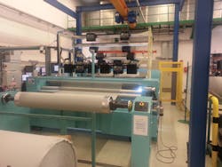
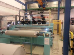
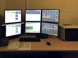
To alleviate this problem, Shelton Vision (Kibworth, Leicestershire, UK; www.sheltonvision.co.uk) has developed an automatic textile inspection system called Shelton WebSpector (Figure 1). The system ensures that a fabric producer can maximize the profit from each batch of fabric produced, while providing relevant data to enable improvements to be made to the production process.
The system incorporates a number of line-scan cameras and associated light sources to enable a range of defect types to be detected consistently across the full width and along the full length of a processed fabric batch. The inspection may take place on the output of a final processing machine or on a purpose-built, high-speed fabric transport machine running from reel to reel at approximately 10 times manual inspection speed. As the fabric is running under the cameras, software detects defects and classifies and grades them by type and severity.
After analyzing and classifying the defects, an electronic defect map of the fabric is automatically created with defect images recorded as well as a complete video of the fabric surface. Usually the fabric will be processed in a large batch that is then cut to smaller rolls as the unit of sale according to customer demands.
Prior to cutting the fabric into the lengths desired by the customer, an operator can review the defect map in terms of the commercial validity and then use the system to create an optimized cutting plan which is generated in virtual form. Once approved, the plan can be transferred to a manual or automatic cutting machine and software can control the cutting machine to ensure the accurately calculated cut plan is faithfully performed.
Image capture
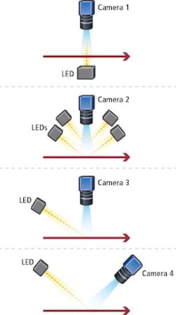
The multiple sets of cameras in the imaging system (Figure 2) are triggered by an encoder on the fabric transport machine to capture images of the fabric under a variety of associated lighting conditions. The cameras employed are Linea CMOS GigE based line-scan cameras from Teledyne DALSA (Waterloo, ON, Canada; www.teledynedalsa.com) and the illumination is from LED light sources positioned at various angles to the fabric, mainly concentrated on the face side, but sometimes on both the face and rear side.
Often the defects do not present any contrast to the surrounding fabric and may be as a result of the surface being snagged, or from an impression created during winding. To detect unacceptable raised features in the fabric, or impressions made on fabric by seams between layers of material on a wound roll, an illumination technique was developed to enable reliable detection for point-raised defects, such as snags, or plucks and for impressions due to large foam holes and seam impressions.
In this case, a set of Linea CMOS GigE line scan cameras mounted above the fabric capture images of the material as it is illuminated by an LED light source positioned at a shallow angle of incidence to the fabric. Although virtually all of the light is reflected out of the field of view of the camera when surface features are present, the light is scattered and enters the camera to reveal the raised features or impressions.
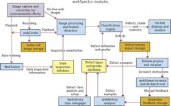
Once the cameras have acquired the line-scan images of the fabric, the images are transferred to a PC where the images are processed by a set of WebSpector image processing and feature detection modules which determine the defect type, severity and whether parts of a defect image need to be 'joined' to other parts of similar defects in the same location.
Training course
Before fabric can be inspected, the system must be trained to understand the characteristics of each of the individual styles of fabric that are being manufactured. To do so, when a batch of a specific fabric is first run through the system, the Shelton Vision webTrainer software performs an analysis on the first few meters to determine how the parameters of the detection algorithms should be set to detect any defects without highlighting any features of the fabric inherent to its natural appearance.
Once the system has completed the training process, the settings that are automatically created for the image processing and feature detection algorithms are stored on a database (Figure 3). When the same fabric style is next run through the system, the settings for that fabric can be relayed to the image processing and feature detection software.
Having identified the characteristics of the defects, they must be classified and graded to ensure the correct action is taken. To do so, a library is first populated with all the images of defects that have been detected by the system. From that library, quality control personnel classify the defects into a number of categories used by the company, such as holes, stains, snags or knots.
Each defect image detected has up to 33 mathematical properties that can be used to describe the defect. This allows each class of defect to be subdivided into five graded categories according to their mathematical parameters, such as size and contrast. The classification and grading process enables the flaws in the material to be managed in a flexible manner. Because each of the defects are stored by type and grade, the user of the system can choose to accept or reject flaws according to their type, severity, or any combination of the two.
After the classification has been set up and 'exported' back into the inspection system, the classification engine uses the properties of the defects that are identified during a production run in real time to characterize each of the defects into the predefined classes. A database stores the various defect types and grades associated with each type of fabric or customer requirements, from where they can be accessed each time identical fabric is processed by the system.
On the map
During the commissioning process, however, it is important to validate the effectiveness of the system. To do so, Shelton VisionWebCorder software captures video from each of the cameras sets as the fabric moves through the system. Next, the defect map created by the system (that highlights the defects found in the material) is replayed in synchrony with the fabric as it is manually inspected on an inspection table.
The manual inspection of the fabric may reveal defects that were not highlighted on the virtual map as a defect due to low sensitivity settings. If so, the video can be checked to ensure the defect has been captured and the commissioning engineer can then adjust the sensitivity setting to bring the defect onto the map. Crucially, the engineer can then replay the section of the video containing the defect through the detection software to ensure that the sensitivity change has the desired effect and does not disrupt other settings.
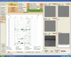
Once installed in a production environment, the system displays the defects that are occurring on the fabric as it passes through the vision system on the defect map. The display shows the length and the width of the fabric under inspection and highlights the types of defects in a color-coded key. Each time a defect is detected, the defect is also highlighted in an on-screen window indicating which camera set in the system has detected it. If a large defect has been identified by the system, the system underscores that defect on the display to ensure that it is more visually obvious to an operator.
Prior to cutting the material, an operator reviews a history of the inspection process on the defect map to ensure that it will be commercially acceptable (Figure 4). Because each of the defects has been classified into type, an operator can commercially review a large batch of fabric in a short time.
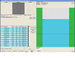
Following the review of the map, the system can generate an optimized cut plan that produces the best quality product with lower defects, or one which produces the highest yield. Because the defects in the fabric are in virtual form, an operator can also determine the effects on yield and quality by applying commercially acceptable tolerances and rerunning the process. The cut plan itself displays the width and length of the material and highlights where cuts and cut outs are to be made, and where any faults must be manually over marked (Figure 5).
Fabric stretch
In many cases, automotive fabric can stretch as it is passed through the cutting process compared to when it was transported through the inspection process. If unchecked, the discrepancy between the data in the cut plan and the actual physical length of the fabric could cause material to be cut erroneously.
To solve this, infrared based ink can be sprayed onto the fabric at known intervals on the edge of the fabric during the inspection process. By detecting the ink spots using a sensor as the roll of fabric is unwound prior to cutting, the system can mathematically calculate and apply a stretch factor between the virtual cut plan and the fabric to ensure that the material is cut precisely. The fabric is then re-rolled onto smaller rolls prior to shipment.
To enable fabric producers to use the inspection data for process improvement, the system also stores a history of the defects that are detected. By analyzing that data, a user can investigate the most commonly occurring defects that have occurred over a fixed period of time. In doing so, the creation of the defect can be related back to possible causes in the production process, which may need to be fine tuned to prevent the same situation from reoccurring to improve the quality of the finished product.
Mark Shelton, Director, Shelton Vision, Kibworth, Leicestershire, UK (www.sheltonvision.co.uk)
Manufacturers listing
Shelton Vision Systems
Kibworth, Leicestershire, UK
www.sheltonvision.co.uk
Teledyne DALSA
Waterloo, ON, Canada
www.teledynedalsa.com
